UML (Unified Modeling Language) is a tool in software engineering for visualizing, specifying, constructing, and documenting software system artifacts. One of the most widely used UML diagrams is the Use Case Diagram, which helps in modeling system functionality from the user's perspective.
What is a UML Use Case Diagram?
A Use Case Diagram is a high-level visual representation of how users (actors) interact with a system. It belongs to the behavioral category of UML diagrams, as it focuses on depicting system functionality and user interactions rather than its structure. It identifies the primary functions and the relationships between actors and use cases, helping to understand system behavior and user interactions.
Key Components of a Use Case Diagram
- Actors – Represent users or external systems that interact with the system.
- Use Cases – Depict functionalities or actions performed by the system.
-
Relationships – Define connections between elements, including:
- Associations – Lines that connect actors to use cases, showing interactions.
- Generalization – Represents inheritance between actors or use cases.
- Include – Represents mandatory dependency where one use case always invokes another.
- Extend – Represents optional behavior that extends another use case.
- System Boundary – Defines the scope of the system.
-
Extension Points – Specific locations within a use case where additional behavior can be added via
<<extend>>.
UML Use Case Diagram Notation
Actor
An actor represents an external entity (user or system) that interacts with the system. It is depicted as a stick figure:
![]()
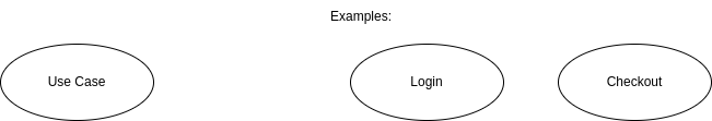
Use Case
A use case represents a specific function or process performed by the system. It is depicted as an oval:
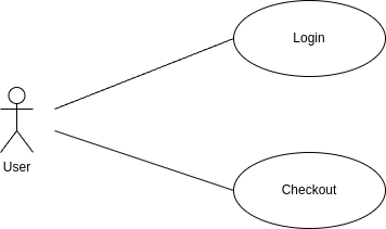
Association
An association is a line connecting actors to use cases, indicating interaction:
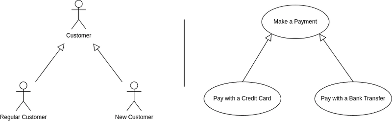
Generalization
A generalization relationship represents inheritance, where a specialized use case or actor inherits behavior from a more general one. It is depicted using a solid line with an unfilled arrowhead:
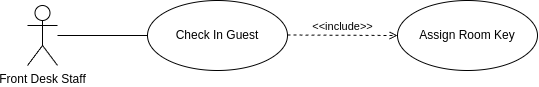
Include Relationship
An include relationship signifies that one use case always invokes another. It represents mandatory behavior where the base use case is incomplete without the included functionality. All included use cases must be shown in the diagram as they represent essential components of the system functionality. It is represented by a dashed arrow labeled <<include>> pointing from the base use case to the included use case.
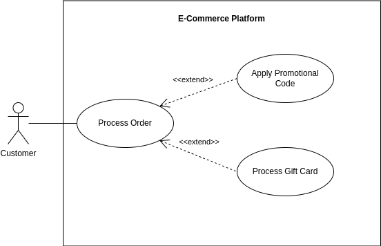
Extend Relationship
An extend relationship shows optional behavior that may be added to a base use case under specific conditions. The base use case is complete on its own, and the extending use case only executes when certain conditions are met at specified extension points. Not all possible extensions need to be shown in the diagram since they represent optional enhancements rather than mandatory behavior. It is represented by a dashed arrow labeled <<extend>> pointing from the extending use case to the base use case.

System Boundary
A system boundary is a rectangle enclosing all use cases, defining the scope of the system.
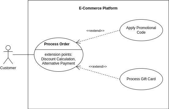
Extension Points
Extension Points define specific locations within a use case where an <<extend>> relationship can introduce additional behavior. They indicate where an extending use case may insert its logic without modifying the base use case.
When to Use a Use Case Diagram?
- When defining system requirements.
- To communicate system behavior with stakeholders.
- During initial design discussions.
- As a reference for development and testing teams.
Conclusion
UML Use Case Diagrams offer a clear and structured way to visualize system interactions and functionalities from the user's perspective. Their value comes from simplifying complex systems into understandable components that represent real-world usage scenarios. By mapping actors, use cases, and their relationships, these diagrams help teams define accurate requirements, communicate system behavior effectively, and maintain focus on user needs throughout the development process. From initial design discussions to testing and implementation, Use Case Diagrams serve as a valuable reference that ensures all stakeholders share a common understanding of what the system should accomplish.

Top comments (0)