A UML Sequence Diagram is a type of interaction diagram that illustrates how objects interact in a particular sequence of time. It captures the dynamic behavior of a system by detailing message exchanges between objects.
Sequence diagrams are widely used in software design to model workflows, use case realizations, and system interactions.
Why Use Sequence Diagrams?
- Visualizing Object Interactions: Shows how different components communicate.
- System Behavior Documentation: Helps document interactions in software.
- Clarifying Requirements: Aids in understanding complex processes.
- Design and Validation: Ensures correctness before implementation.
UML Sequence Diagram notation
UML Sequence Diagrams use a set of standard notations to represent interactions between objects over time. Main notations include elements like lifelines, messages, activations, and control structures, helping to illustrate how different components collaborate within a system.
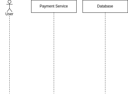
1. Lifeline
A lifeline represents an object or actor that participates in the interaction. It is depicted as a dashed vertical line under an object or actor symbol.
- Actors: Represent external users or systems interacting with the system.
- Objects (Participants): Represent system components.
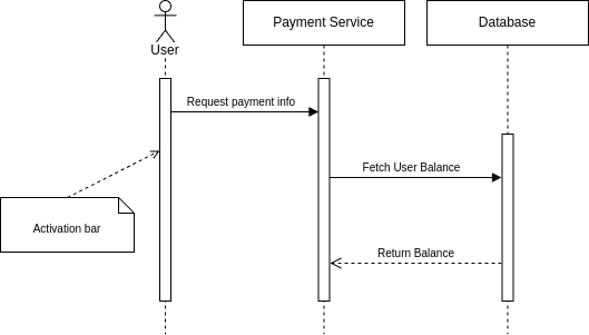
2. Activation (Execution Occurrence)
An activation box (also called an execution occurrence) represents the period during which an object is actively processing a message. It is depicted as a thin rectangle drawn over the lifeline of an object, indicating that the object is performing an operation.
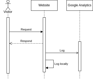
3. Message Types
Messages represent the communication between objects. They define how information flows between participants during an interaction. Different message types indicate whether the sender expects a response, how control is transferred, and whether the interaction is synchronous or asynchronous. These messages help describe method calls, event triggers, and object interactions, providing a detailed view of how the system behaves dynamically.
- Synchronous Message: The sender waits for a response.
- Asynchronous Message: The sender does not wait for a response.
- Return Message: A response after processing.
- Self Message (Recursion or Internal Call): When an object calls itself.
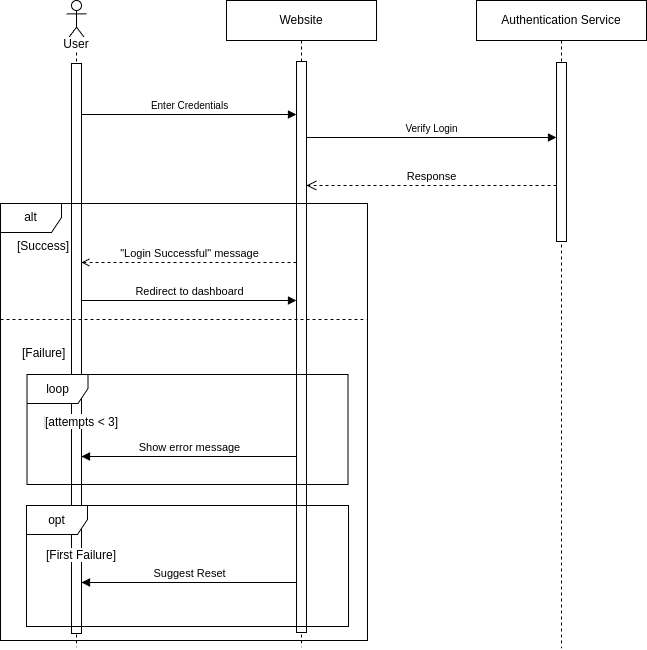
4. Combined Fragments (Control Structures)
Combined Fragments are used to represent control structures like loops, conditionals, parallel execution, and exceptions.
They are drawn as a rectangular frame with an operator keyword (e.g., alt, loop, opt) in the top-left corner.
All Combined Fragments and Their Usage
| Fragment | Purpose |
|---|---|
alt (Alternative / If-Else Condition) |
Represents a choice between two or more mutually exclusive paths (if-else logic). |
opt (Optional Execution) |
Represents an optional action that occurs only if a condition is met (like if without else). |
loop (Iteration / Repetition) |
Repeats a sequence of messages as long as a condition remains true (for/while loops). |
par (Parallel Execution) |
Allows concurrent execution of multiple sequences (multithreading, async tasks). |
ref (Reference to Another Diagram) |
Calls another sequence diagram instead of duplicating interactions (modular design). |
break (Interrupt / Exit Flow) |
Immediately exits from a sequence when a condition is met (early termination). |
critical (Critical Section / Mutex Locking) |
Ensures a sequence is executed without interruption (atomic operations, locks). |
neg (Negative Sequence / Invalid Case) |
Represents an invalid or forbidden sequence that must not happen. |
assert (Mandatory Execution) |
Ensures that a sequence must always occur at a specific point. |
ignore (Ignore Messages) |
Specifies that certain messages should be ignored in this part of the sequence. |
Advanced Features
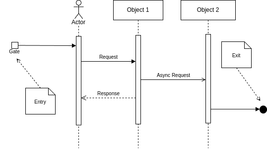
1. Gates (Entry & Exit Points)
Gates are a mechanism to represent entry and exit points for messages in a diagram. They act as connection points between different sequence diagrams or within a composite structure, allowing modularization and simplification of complex interactions.
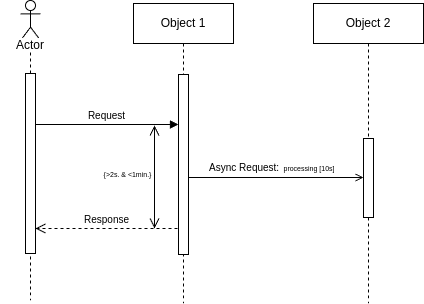
2 Timing Constraints
Timing constraints define the time-related conditions that must be met during interactions between objects. These constraints can specify delays, timeouts, or deadlines for message exchanges.
Best Practices for UML Sequence Diagrams
- Keep It Simple: Avoid clutter with unnecessary details.
- Use Clear Labels: Ensure messages and actors are well-named.
- Organize Lifelines Logically: Place related objects close together.
- Use Fragments for Control Logic: Helps in better readability.
- Ensure Readability: Maintain proper spacing and layout.
Conclusion
UML Sequence Diagrams provide a dynamic view of object interactions, making them essential for software design. By mastering these notations, you can model workflows effectively and improve system understanding.

Top comments (0)