
Introduction
Kenya Power, our local power distributer, owns Kenya Electricity Generating Company, 218 million dollars despite being a monopoly in the country. The fast declining revenues has been attributed to theft facilitated by it’s own employees and it’s own legacy structure.
Innovative technologies such as smart grids, smart meters combined with technologies such as Distributed Ledger technologies and Internet of Things to curb the massive theft.
In this tutorial we will be using two technologies Distributed Ledger Technology and Internet of Things to turn on lights for a period of time. This will be based on how much money we will be sending to our account. IOTA tokens will represent the amount of money we will be sending to our account. All transactions will be recorded on the Tangle. Hopefully with this level of traceability, it will be harder for actors to steal information from electricity distribution systems.
Some of the benefits of Distributed Ledger Technology, to be specific IOTA and IoT in the energy sector are
- Transparency, make supply chains more transparent, leading to real price for value and linking milestones to actions.
- Trust, enable creation of marketplaces for sourcing in an ecosystem.
- Efficiency, lower cost of compliance and lower cost of reconciliation (between subsidiaries).
- Control and security, where auditing, cost, control and accounting will be impacted as the handling of payments can be streamlined and automated.
- Zero transaction fees.
- Can handle micro-transactions (very small amount of money).
- Can be used with very basic sensors.
- Quick confirmation time.
- Highly secure from attacks.
Requirements
The following background knowledge will come in handy
- Node js.
- Javascript.
- Typescript.
- Python.
- Some knowledge on IOTA Blockchain or Blockchains in general, Electronics and Mqtt.
This tutorial does not cover the basic concepts of Mqtt, Mam or IOTA Payments. You can learn more about this technologies here.
- Mam https://www.youtube.com/watch?v=Nnwn_o_ZBFU&feature=emb_title
- Mqtt https://www.hivemq.com/mqtt-essentials/
- IOTA Payments https://docs.iota.org/docs/client-libraries/0.1/account-module/js/get-started
Hardware Requirements
The components required are:
- ESP 8266-01 https://ktechnics.com/shop/wireless-devices/rfidnfc/esp8266-esp-01-serial-wifi/
- LM1117T Transistor https://ktechnics.com/shop/intergrated-circuits/voltage-regulators-ics/lm1117t-lm1117-low-dropout-voltage-regulator-3-3v/
- 10uF Capacitor https://store.nerokas.co.ke/index.php?route=product/product&path=81_117&product_id=961
- Switch https://store.nerokas.co.ke/index.php?route=product/product&product_id=1995&search=switch&page=3
- 10k Ohm Resistor (quantity 2) https://store.nerokas.co.ke/index.php?route=product/product&product_id=1675&search=resistor+10&description=true
- Breadboard https://ktechnics.com/shop/prototyping/breadboard-mb102-solderless-type-830-points/
- Green Led https://ktechnics.com/shop/components/capacitors/light-emitting-diode-led-green/
- 5V Power Supply
- 470 Ohm Resistor https://store.nerokas.co.ke/index.php?route=product/product&product_id=451&search=470+&description=true
- 5v 1 Channel Relay https://store.nerokas.co.ke/index.php?route=product/product&product_id=1679&search=switch&description=true
- Male to Male wires https://store.nerokas.co.ke/index.php?route=product/product&product_id=120&search=male+to+male&description=true
- Male to Female wires
- Bulb https://www.jumia.co.ke/lotus-enhanced-led-9w-b22-warm-white-bulb-757050.html
- Bulb holder https://sky.garden/product/PnsY7J3N
- Usb programmer https://www.aliexpress.com/item/32985707091.html?spm=a2g0o.productlist.0.0.275a759bLItMFS&algo_pvid=0eb05015-3a2d-46d4-83ee-049fbf63e31e&algo_expid=0eb05015-3a2d-46d4-83ee-049fbf63e31e-0&btsid=0ab50f0815982177184654489e2b0e&ws_ab_test=searchweb0_0,searchweb201602_,searchweb201603_
PS: You can probably get all these components, half the price at Aliexpress .
Warning Use proper care when handling large current.
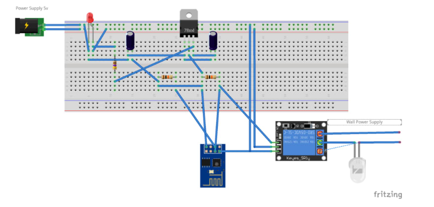
Step 1: Circuit set up
The first step is to build up the circuit. The designs were done with both EagleCad and Fritzing and also for EagleCad.
Set up the circuit as shown in the figure below. You can open the following image by downloading fritzing and opening the fritzing file in the url https://github.com/peterokwara/pay-for-light/tree/master/schematics/Fritzing
You can also use EagleCad to open the circuit. To do this, you can open the Board and Schematics file after you get them from here

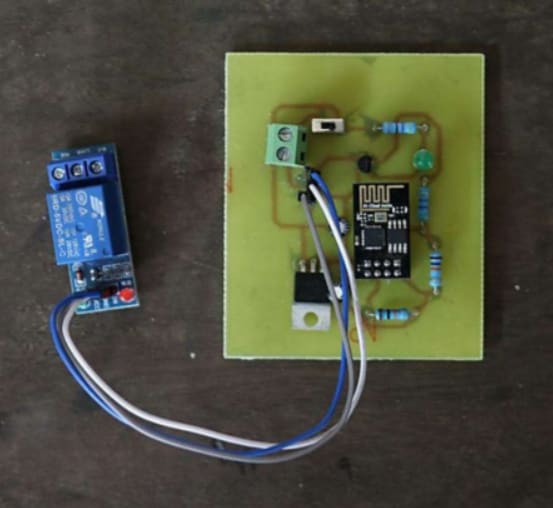
The EagleCad design can also be etched on to a photochromatic board. The final look of the board after it has been etched on a board based on the board when disconnected.
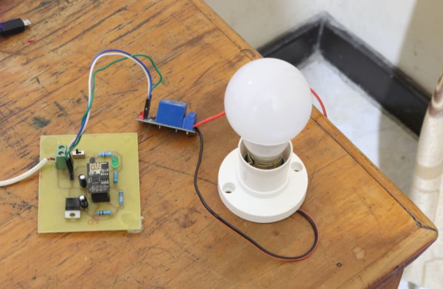
When connected to a bulb and power supply.
NB: The project can still be done on a breadboard. It's not a must for one to etch it on a board.
Step 2: Adafruit IO
Adafruit IO is a cloud service where one can connect IoT devices to send and receive data from it. It acts like a broker in the cloud.
Create an account by going to https://io.adafruit.com/ and click on sign up. One you have signed up or you have already have an account you can now sign in.

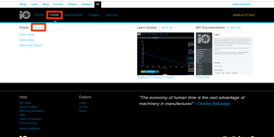
Once we are able to login, go to the Feeds tab an click on View all Feeds as highlighted below.
The first thing we would like to do is to create a group under which we will put our feed. On Actions, we click on Create a new group.

Call the new group pay-for-light and click Create.

Create a new feed by clicking on Actions and select Create a New Feed.
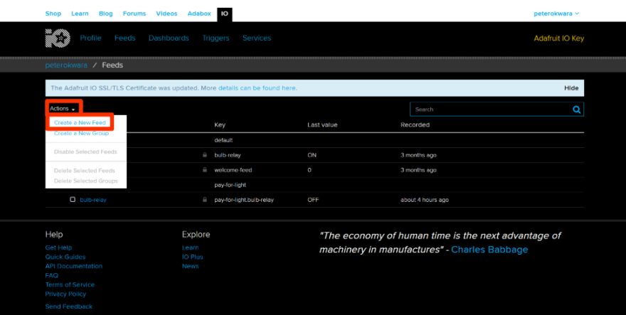
For the new feed, we will call it as bulb-relay. We will add it to the group we just created. The group being pay-for-light. Once we do this we can now click Create.

We can now go back to the feed and get our Adafruit IO Key. We click on the Adafruit IO Key.
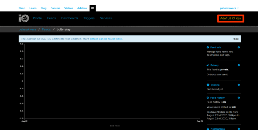
Under username, we see our Active Key. This is the key we will use to connect to our Adafruit IO account to post the mqtt information.

Step 3: Wi-Fi set up
Use the code shown below to set up Wi-Fi. What it does is that it takes in the WIFI_ESSID and WIFI_PASSWORD and tries to connect to your Wi-Fi network. If it successfully connects, it prints out Connection successful and the network information. If it is already connected, it will print Already connected.
def connect():
""" Connects to a wifi hotspot.  Takes in the wifi username and the wifi password from a config.py file and  tries to connect to the wifi username defined.

Args:
    None.
Returns:
    A print statement that states whether the *nodemcu* model is connected
    to a wifi network, already connected to a wifi network and the network
    details.
"""

import network
import config

ssid = config.WIFI_CONFIG['WIFI_ESSID']
password = config.WIFI_CONFIG['WIFI_PASSWORD']
station = network.WLAN(network.STA_IF)

if station.isconnected() == True:
    print("Already connected")

station.active(True)
station.connect(ssid, password)

while station.isconnected() == False:
    pass

print("Connection successful")
print(station.ifconfig())
Create a config file that the code will use to fetch the username and password, and use it to connect to the Wi-Fi. Ensure you enter your Wi-Fi name and password to the config file to connect to.
MQTT_CONFIG = {
    'SENSOR_ID': '',
    'MQTT_HOST': '',
    'PORT': '',
    'PUB_TOPIC': ''
}
WIFI_CONFIG = {
    'WIFI_ESSID': '',
    'WIFI_PASSWORD': ''
}
Setup the main code to look like this. It's main purpose is to connect to the wifi network we specified in the configuration file.
import wifiSetup

# Connect to wifi hotspot
wifiSetup.connect()
Step 4: Configuration Setup
Set up the config file with the following default values. Assuming we followed all the settings for Adafruit IO we used when setting up, we would have the following default values below. The only values we would need to replace are the wifi configurations, the adafruit io username and adafruit io key.
WIFI_CONFIG = {
    'WIFI_ESSID': '',
    'WIFI_PASSWORD': ''
}

MQTT_CONFIG = {
    'ADAFRUIT_IO_URL': 'io.adafruit.com',
    'ADAFRUIT_USERNAME': '',
    'ADAFRUIT_IO_KEY': '',
    'ADAFRUIT_IO_FEEDNAME': 'pay-for-light.bulb-relay'
}
Step 5: Relay
Import the following files. This includes the Mqtt libraries, config libraries, wifi connection file among others.
import os
from umqtt.simple import MQTTClient
import connectWifi
import time
import config
import json
import sys
import machine
from machine import Pin
Next step is to connect to wifi. Call the function the function connect from the connectWifi python file.
# connect to wifi
connectWifi.connect()
Set up the GPIO pin we will use to turn on or off the pin. We want to use GPIO_2 for this.
# set GPIO_2 pin as an output pin
RPin = Pin(2, Pin.OUT, value=0)
Manually generate a client id for Mqtt.
# generate a client id
random_num = int.from_bytes(os.urandom(3), 'little')
mqtt_client_id = bytes('client_'+str(random_num), 'utf-8')
The next step is to connect to the Adafruit IO Service in the cloud.
# import configuration setup
ADAFRUIT_IO_URL = config.MQTT_CONFIG["ADAFRUIT_IO_URL"]
ADAFRUIT_USERNAME = config.MQTT_CONFIG["ADAFRUIT_USERNAME"]
ADAFRUIT_IO_KEY = config.MQTT_CONFIG["ADAFRUIT_IO_KEY"]
ADAFRUIT_IO_FEEDNAME = config.MQTT_CONFIG["ADAFRUIT_IO_FEEDNAME"]
We then set up a function to turn the relay on.
def relay_on():

    # Sends a message to the broker that the relay has been turned on, and then turns on the relay.
    send("Relay on")
    RPin.on()
And a function to run off the relay.
def relay_off():

    # Sends a message to the broker that the relay has been turned off, and then turns off the relay.
    send("Relay off")
    RPin.off()
Set up a function to send a message to the broker. The broker in this case is the Adafruit IO service in the cloud. This takes in the feed and the data we need to send to our Mqtt service.
def send(data):

    # Sends a message to the broker.
    client.publish(mqtt_feedname, json.dumps(data))
We then subscribe to messages we will receive from our Mqtt service in the cloud which is Adafruit IO. If the message is on, we call the function to turn on the relay. If the message is off, we want to turn off the relay.
def cb(topic, msg):

    # Callback which is called when subscribed data is received.
    print('Received Data:  Topic = {}, Msg = {}'.format(topic, msg))
    command = msg.decode('ASCII')
    if command == "ON":
        relay_on()
    elif command == "OFF":
        relay_off()
On to the main method. We first try to connect to our Mqtt Server. If this fails we, print that we are not able to connect to the Mqtt server. We then sleep for 10 minutes and reset the microcontroller.
def main():

    # Connect to a mqtt server
    try:
        client.connect()
    except Exception as e:
        print('could not connect to MQTT server {}{}'.format(type(e).__name__, e))
        time.sleep(10)
        machine.reset()
We then call the callback function and set it up within the main function.
# set the callback
client.set_callback(cb)
We call the subscribe function and the feed we want to subscribe to and send a test message.
# subscribe to a given feed name
client.subscribe(mqtt_feedname)

# send test message
send("Is this... now?")
Then we want to check for incoming messages or commands. This command runs infinitely. In case we get any errors, we send over, we print an error message, sleep for 10 seconds then reset the microcontroller.
# check for incoming messages/commands
while True:
    try:
        if True:
            # Blocking wait for message
            client.wait_msg()
        else:
            # Non-blocking wait for message
            client.check_msg()
            # Then need to sleep to avoid 100% CPU usage (in a real
            # app other useful actions would be performed instead)
            time.sleep(1)
    except OSError as e:
        print('Failed to connect to MQTT broker. Reconnecting...')
        time.sleep(10)
        machine.reset()
Step 6: Push files
You need to have micropython running on the esp for it to work, I normally use esptool to upload the firmware on to the esp.
Plug in the esp8266-01 on to an esp programmer as shown below and plug it in to your computer.

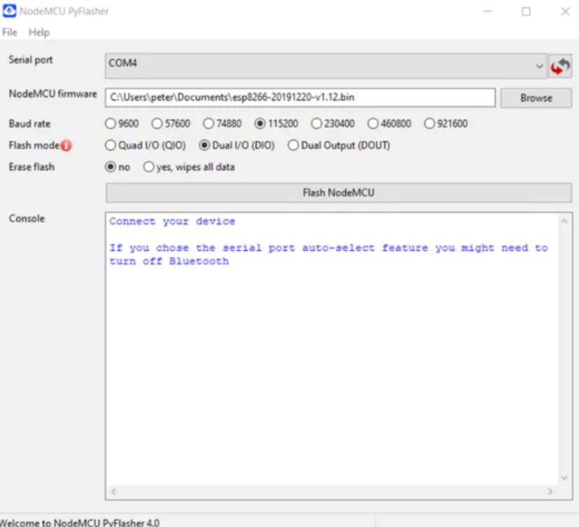
Identify the port in which the programmer is connected to. You can do this by going to the device manager. In this case it's COM4.

The next step was to download the firmware. The firmware is available from here. Once the firmware was downloaded, I opened the Nodemcu software and set up the Serial port and the firmware. Baud rate was set to 115200 and flash mode set to Dual I/O.
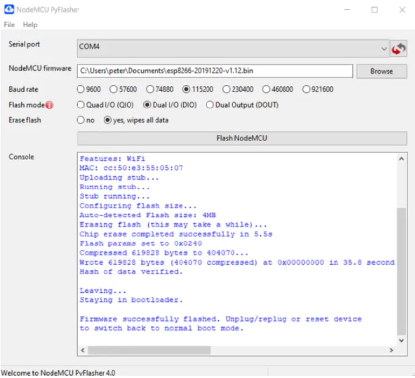
The next step was to press the flash switch on the esp programmer and click on the Flash NodeMCU button on the NodeMCU PyFlasher software. The image below shows what happens when you successfully flash the firmware on to the esp.
For UNIX users, an alternative way of setting up is using the terminal. This requires you know the location of the downloaded firmware and the port the NodeMCU is connected to. This is:
sudo apt install python-pip
sudo pip install esptool
Erasing the flash
sudo esptool --port /dev/ttyUSB0 erase_flash
Uploading the flash to the device
sudo esptool.py --port /dev/ttyUSB0 --baud 115200 write_flash --flash_size=detect 0 ~/Downloads/esp8266-20171101-v1.9.3.bin
To test if the board is working well, we will try to access the board and turn on the on board LED. To do this on Windows we need to use putty. After installing putty, the next step is setting up the board connection. WE ensure the serial line is COM4, the port the esp programmer is connected to, the speed set to 115200 and the connection type set to serial.

The command I normally run is
sudo esptool.py --port /dev/ttyUSB0 --baud 115200 write_flash --flash_size=detect 0 ~/Downloads/esp8266-20171101-v1.9.3.bin
I wrote the following code to see if the board is working or not. The on board led should turn on and off based on whether pin.on() or pin.off() has been toggled.

To store the python files on the nodemcu, I normally use ampy. Installing it on a windows environment, assuming you have python installed, you run:
pip install adafruit-ampy
Or if you are using Linux or Mac OSX you run:
sudo pip3 install adafruit-ampy
To list the files, remove files or put files on to the NodeMCU, you run:
sudo ampy --port /dev/ttyS4 --baud 115200 ls
sudo ampy --port /dev/ttyS4 --baud 115200 rm <filename>
sudo ampy --port /dev/ttyS4 --baud 115200 put <filename>
To put the 3 files we just created, you run:
sudo ampy --port /dev/ttyS4 --baud 115200 put main.py
sudo ampy --port /dev/ttyS4 --baud 115200 put config.py
sudo ampy --port /dev/ttyS4 --baud 115200 put wifiSetup.py
This all assumes that the port /dev/tty4 you used is the correct one for your machine. Check device manager to know which port your device is connected to.
You can use a Wi-Fi scanner to check if your device is connected. I used Fingbox to check if the NodeMCU is connected to the Wi-Fi network.

To continue with the tutorial, please check out Part 2 here

Top comments (0)