
At some point in your life, you’ve probably been in a situation where you wished you could use a cellular asset tracker to help keep tabs on your stuff. Where you parked the car at a concert, the actual location of that package you ordered three weeks ago, or the whereabouts of that scooter you that’s been helping get you that last mile to work, knowing where the things you care about in life is a valuable thing.
While there might be some generic solutions available, I’m going to show you how to build an all-purpose cellular asset tracker, with features that you can quikcly adapt to suit your specific needs. To build this tracker, the project uses FeatherWing accessory boards from the Adafruit Feather system to allow you to easily customize the project by swapping out different sensors or actuators — no jumper-wires necessary.
This project will be a relatively simple cellular asset tracking solution, but it’s a great base to customize to your needs. It starts with a Particle Boron as the brains of the build. The Boron queries location data from an attached GPS module and displays the coordinates on a small OLED display. All three of the FeatherWing compatible devices attach together using a FeatherWing Tripler, and means zero wiring is required. And since there are hundreds of FeatherWings, you can easily expand the functionality just by swapping out a Wing and modifying your code.
Note : If you’re unfamiliar with GPS and other geolocation technologies used in IoT, the Ultimate Guide to Geolocation can help. Learn what every IoT engineer needs to know about GPS, dead reckoning, cellular, Wi-Fi, and BLE all in one place.
Project parts & tools

Required parts:
- Particle Boron — this project assumes you’ve set up your Boron. If you’ve not done that yet, follow the instructions here before you begin this project.
- Particle FeatherWing Tripler
- Adafruit FeatherWing OLED
- Adafruit Ultimate GPS FeatherWing
Optional, but highly recommended parts
- CR1220 3V lithium coin cell battery — used with the GPS module to keep the real-time clock (RTC) powered and allow warm starts.
- SMA-to-uFL RF adapter cable — Most GPS antennas use an SMA connector, but most boards use smaller uFL connectors. This cable lets you connect them together.
- GPS antenna — A bigger, more powerful antenna that will get you a better satellite fix more quickly.
Tools
- Soldering equipment is needed to connect some of the headers to the FeatherWings and Tripler board.
Note: You’ll most likely also want an enclosure of some kind. In this project, we’ve used a custom laser cut enclosure, but you could 3D print something, or go with an off the shelf solution just as easily. You can download my design files here.
Hardware assembly
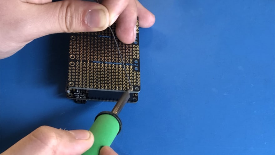
Step 1. Soldering the headers
Some of the FeatherWings in this project will require you to solder the header pins to the boards. To keep the headers square to the board. Place them in a spare breadboard, with the board you want to add pins to on top. This will help you’ll get proper alignment as well as it’s a lot more convenient to solder with the parts firmly in place.

The FeatherWing Tripler uses female headers, but you can use a similar trick as you used with the breadboard. Place the female headers over their respective pins on one of the other FeatherWings, and then place them in the Tripler on top to solder. That way the headers will all line up correctly, and it’s a lot easier to solder.
Attention: make sure you solder the Tripler correctly, or you risk damaging your boards.
Step 2. Assembling your FeatherWings
With the soldering out of the way, you can move on to assembling the project. FeatherWing placement matters. In order to ensure access to the battery port on the Boron, you must place it on the right-hand side of the Tripler. In the middle comes the OLED Feather, and the GPS Wing will be on the left side.
Note: If you don’t use this ordering, you’ll have trouble routing the antenna and battery cables.
At this point, you can carefully attach the antennas to their respective connectors — make sure you use the cellular connector on the top side — and plug in the battery to the Boron.
Step 3. Laser-cut your enclosure or build your own
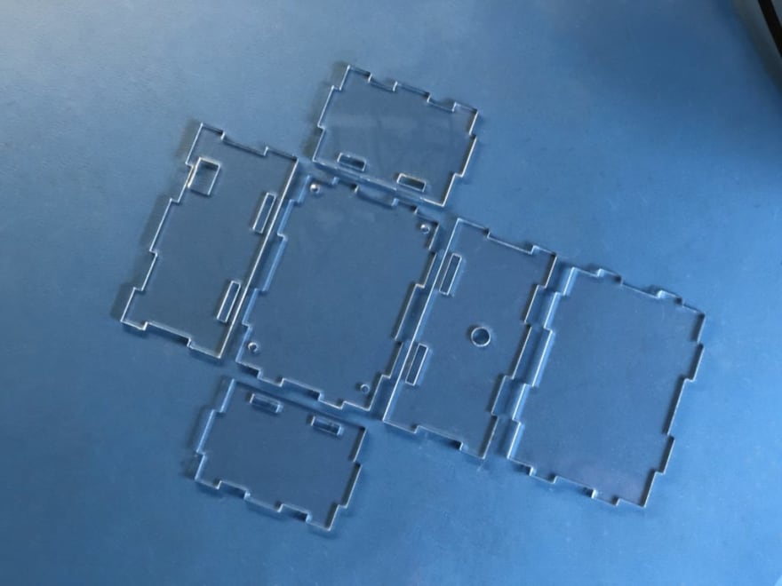
If you’ve made or purchased an enclosure, you can start fitting the project in there now.
Navigating the Boron asset tracker source code
The code for this project is kept relatively simple, so it can easily be customized to suit your individual needs. The code makes use of the TinyGPS++ library to abstract the hard parts of dealing with GPS data and gives you easy to use functions to extract the data you need. That way, you don’t have to reinvent the wheel and go through the hassle of dealing with raw GPS data.
![]()
In a bird’s eye view, the code loops to see if there is GPS data available and hands it to the tinyGPS library for parsing if so. It then checks whether the data coming out is sensible. When that’s not the case, it will give an error output on the display, informing you a fix hasn’t been found. If the data does make sense, it will package it in a nice format and will display the GPS coordinates on the display. That’s also where you could make changes to the information that gets displayed.
Finally, the code will publish a message to the cloud with the GPS information, which can be acted upon on that end using webhooks, or other integrations.
Click here to load the code in your WebIDE — no extra typing required.
If you’re not using the Web IDE share link, make sure to manually include the TinyGPS++ and the oled-wing-adafruit libraries.
Code highlights and commentary
The code for this project is all open source, but I wanted to quickly highlight a few of the most important sections to help give you ideas for where you can modify to suit your needs. Take special note of the line numbers as I’m covering snippets of code below.
The following code will run in a continuous loop, checking to see if new GPS information is available. If there is new data, it will call the displayInfo() function to start processing.
void loop()
{
    display.loop();
    while (Serial1.available() > 0) {
        if (gps.encode(Serial1.read())) {
            displayInfo();
        }
    }
}
The code shown below is taken from the displayInfo() function.
After getting the GPS data and making sure it’s valid, the information is packed into a buffer and displayed on the OLED.
display.clearDisplay();
display.setTextSize(2);
display.setTextColor(WHITE);
display.setCursor(0,0);
snprintf(buf, sizeof(buf), "%f", gps.location.lat());
display.println(buf);
snprintf(buf, sizeof(buf), "%f", gps.location.lng());
display.println(buf);
display.display();
Up next, the code packages the data in new buffers so it has a nice format for output over Serial.
snprintf(buf, sizeof(buf), "%f,%f,%f", gps.location.lat(), gps.location.lng(), gps.altitude.meters()); // Format for Serial logging
Finally, there’s a check to see if we’re not publishing too often. If that’s not the case, then publish the data to the cloud.
if (Particle.connected()) {
    if (millis() - lastPublish >= PUBLISH_PERIOD) {
        lastPublish = millis();
        Particle.publish("gps", pubbuf, PRIVATE);
    }
}
Visualizing your data with Ubidots

To take this project a step further than displaying the coordinates on the OLED, you can send the data to an online platform to display it on a map. There are various services available that offer functionality like this, such as the Particle Google Maps integration.
For this tutorial, I chose to use Ubidots. They offer a great service for ingesting data and plotting it on a map. Plus it’s easy to integrate. You can get the data to them by using a webhook in the Console, and a specific Particle.publish() on the device.
First, create an account on Ubidots. For Ubidots to accept the data as a GPS location, it will look for a specific format in the data it receives. It expects to find a JSON object containing a lat and lng key, with their respective values.
On the device:
To get the data in the format Ubidots expects it, you’ll have to add some bits to the code. The key lines to look at here are line 71 and 86, which create and fill a buffer for Ubidots.
char pubbuf[120];
if (gps.location.isValid() && gps.location.age() < MAX_GPS_AGE_MS) {
    display.clearDisplay();
    display.setTextSize(2);
    display.setTextColor(WHITE);
    display.setCursor(0,0);
    snprintf(buf, sizeof(buf), "%f", gps.location.lat());
    display.println(buf);
    snprintf(buf, sizeof(buf), "%f", gps.location.lng());
    display.println(buf);
    display.display();
    snprintf(buf, sizeof(buf), "%f,%f,%f", gps.location.lat(), gps.location.lng(), gps.altitude.meters());
    snprintf(pubbuf, sizeof(pubbuf), "{\"position\": {\"value\":1, \"context\":{\"lat\": \"%f\", \"lng\": \"%f\"}}}", gps.location.lat(), gps.location.lng());
Create a new buffer to store the Ubidots formatted data in. Then, fill that buffer with the JSON content and the GPS data. Finally, Publish that buffer as a Particle.publish().
In the console:
To get the published data to Ubidots, you can use their API. To do so, you’ll have to create a webhook. Go to the Console, and find the integrations tab on the left. Create a new integration and select a webhook. In the top left, find and select the custom template option. Copy and paste in the following snippet.
{
    "event": "gps",
    "url": "https://industrial.api.ubidots.com/api/v1.6/devices/{{{PARTICLE_DEVICE_ID}}}",
    "requestType": "POST",
    "noDefaults": false,
    "rejectUnauthorized": true,
    "headers": {
        "X-Auth-Token": "replace-this-with-your-token",
        "Content-Type": "application/json"
    },
    "body": "{{{PARTICLE_EVENT_VALUE}}}"
}
Make sure to replace the highlighted X-Auth-Token with your own. You can find said token by going to your Ubidots account, clicking on your profile icon and selecting API credentials.

After you've successfully completed each of the steps, you should now have a functioning cellular asset tracker that will display its GPS coordinates on the screen, as well as publish them to the cloud, where you can work with them in different ways to serve your purpose.
Where will you take you take your asset tracker?
Starting with this project, you can use it as the basis of a car tracking system, a geofence for your pets or kids, track shipping containers or do something as mundane as making internet connected scooters. The possibilities are certainly there and so are the basics to start from.
![]()
Take a look over at Hackster to get inspiration for projects you could build next. Additionally, share your thoughts and ideas on our Particle forum, where you can brainstorm and get project advice. It’s also a great place to ask questions, with many of our members being eager to help out.
Now go forth and track something that matters to you.
The post Learn how-to build this cellular asset tracker with a Particle Boron appeared first on Particle Blog.

Latest comments (3)
This a fun project! How would you go about building a Particle.variable for gps.location.lat and gps.location.lng?
Any idea on battery usage and expected time between charges ?
Battery usage is a tricky thing. For this project it was more important to show a functional proof of concept, than it was to optimize for either power or data efficiency. As such, it was publishing its coordinates every 10 seconds regardless of movement. In this state, it lasted roughly 2 days on a 2000mAh battery.
There are many ways to improve battery life, by making the code a little bit smarter. It usually isn't necessary to publish as often as I did, and fewer points would mean both power and data usage should go down. You could check the difference in location between GPS queries to dynamically adjust the sampling frequency based on distance traveled. Adding an accelerometer would allow it to stop sampling/sending until the device actually starts moving, and sleep otherwise.
Sleeping either the GPS and the cellular modem in between their respective publishes or queries would also help cut down on data and power usage quite a bit.
For some uses you want high granularity in location data, in others you only want to get notified after it changed its location by a certain amount. In some places you can hook up a solar panel, and in others you might be able to recharge every so often.
In the end, it really comes down to your application to decide the best way to go about optimization.