One of the widely used protocols for inter-device communication, especially in the realm of microcontrollers and integrated circuits, is the Inter-Integrated Circuit, or I2C, protocol.
Understanding the Basics
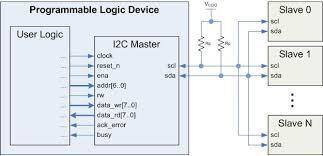
At its core, I2C is a synchronous, multi-master, multi-slave serial communication protocol. This means that multiple devices can communicate with each other over the same bus, with one or more devices acting as masters initiating communication and others as slaves responding to the master's commands. The synchronous nature of the protocol means that data is transferred based on a shared clock signal, ensuring precise timing.
Hardware Configuration
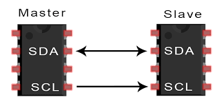
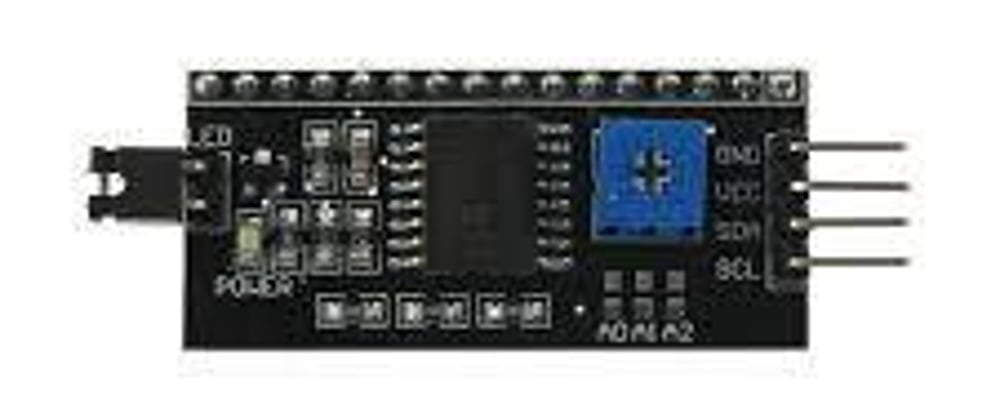
I2C communication typically involves two wires: a Serial Data Line (SDA) and a Serial Clock Line (SCL). These wires facilitate bidirectional communication between devices on the bus. Both lines are pulled up to a positive voltage level (usually 3.3V or 5V) using resistors, and devices connected to the bus are equipped with open-drain or open-collector outputs to drive the lines low.
Addressing
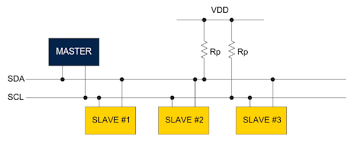
Each device on the I2C bus is assigned a unique 7-bit or 10-bit address. When initiating communication, the master device sends the address of the slave it wishes to communicate with along with a read/write bit indicating the direction of data transfer. This addressing scheme allows for the connection of multiple devices without conflicts, as each device only responds to its specific address.
Data Transfer
Data transfer in I2C occurs in bytes. After addressing a specific slave device, the master can send or receive data from the slave. During data transmission, the SDA line is stable when the clock signal on the SCL line is high, allowing for the data to be read or written. When the clock signal transitions from high to low, the data on the SDA line is sampled.
Start and Stop Conditions
Communication on the I2C bus begins with a start condition, where the SDA line transitions from high to low while the SCL line remains high. This indicates the start of a new data transfer sequence. Conversely, a stop condition occurs when the SDA line transitions from low to high while the SCL line remains high, signaling the end of the data transfer.
Clock Speed
The speed of communication on the I2C bus is determined by the frequency of the clock signal. Standard mode operates at a maximum speed of 100 kHz, while Fast mode extends this to 400 kHz. Additionally, there are high-speed modes such as Fast Mode Plus (Fm+) and Ultra-Fast Mode (UFm), which support speeds of up to 1 MHz and beyond.
Advantages and Applications
The I2C protocol offers several advantages, including simplicity, flexibility, and support for multi-device communication. Its ease of implementation makes it ideal for various applications, including sensor interfacing, real-time clock modules, EEPROM memory, and communication between microcontrollers and peripheral devices.
Conclusion
In the ever-expanding landscape of embedded systems and IoT devices, efficient communication protocols like I2C play a crucial role in enabling seamless data exchange between components. With its simplicity, versatility, and robustness, the I2C protocol continues to be a cornerstone in modern electronics, empowering engineers to design innovative and interconnected systems with ease. Understanding its principles and intricacies is essential for anyone venturing into the realm of embedded systems and microcontroller programming.


Top comments (0)