
Hi Friends! I welcome you on board. Happy to see you around. In this post today, I’ll walk you through Flexible PCB in detail.
Flexible circuit boards are commonly used in laptop computers, cell phones, and digital cameras. These boards can fit in hard-to-reach places due to their lightweight and compact structure. They range from single-layer boards used in simple electronic units to multilayer complex boards used in advanced electronic applications. You can twist, fold and even flex these boards into a rolled-up configuration. Flexible boards exhibit three-dimensional packaging geometry and offer wiring solutions to the electronic applications where rigid boards fail to meet the requirements. They cover less space as they come with the thinnest substrate material as thin as 0.0004 inches. The inception of flex boards has replaced many types of wiring done by hand, reducing the overall price of electrical wiring by up to 70%.
I suggest you read this post all the way through as I’ll cover each and everything related to Flexible PCB including definition, types, material, manufacturing process, price & applications.
Let’s get started.
Definition
A flexible PCB is a special type of circuit board that you can twist, fold and bend into any desired shape. In the flex boards, the polyimide substrate material is used that comes with remarkable heat resistance, making it a right fit for solder mounting components. They work perfectly in extreme environments and can withstand shocks and vibrations due to their flexible nature.
Types of Flexible PCB
The types of flexible circuit boards include:
Single-Sided Flexible PCB
The single-layer Flexible PCB, also known as single-sided PCB, carries only one conductive copper layer. The conductive layers sit on the flexible dielectric film. Electrical components can be added on only one side of the board.

Double-Sided Flexible PCB
Conductive copper layers are added on both sides of the board in a double-sided flexible PCB, increasing the wiring density per unit area. Electrical components can be attached on either side of the copper layer.

Multiple Layer Flexible PCB
The multi-layer flexible PCB carries three or more conductive copper layers. These layers are separated by a dielectric material. Multilayer units exhibit higher reliability, better thermal conductivity, and offer easy assembly. Polyimide substrate material is used for flexible boards that is 1/3 lighter than the substrate material used in rigid boards.

Rigid-Flex PCB
The rigid-flex designs have the ability of both flexible and rigid circuit boards. These boards come with higher component density compared to other traditional circuit boards.
HDI Flexible PCB
The HDI (high-density interconnect) circuit boards are the type of flexible boards that guarantee reduce package size and exhibit remarkable electrical performance. The thin substrate material is used for the production of HDI flexible boards, ensuring seamless layout design and better construction.
Material
You can pick from three types of substrate materials available for the manufacturing of flex boards. First is polyester that is mainly employed in low-end products, next is polyimide (PI) that is commonly preferred in flex boards and is more expensive than fiberglass or FR-4 substrate material used in rigid circuit boards. Third is fluoropolymer that is widely used in military and aerospace products.
When you compare these three susbtrate material mentioned above, you’ll notice the PI film exhibits highest dielectric constant and shows remarkable electrical properties and resistance towards high temperature, which means PI film stays flexible and doesn’t soften when heated at a high temperature.
Standard PI films don’t exhibit good resistance to tears and humidity, however, picking the quality and upgraded PI films can remove such issues. An adhesive or special base material is used in flex circuits for its layers to attach.
Solder mask is not used in flex boards, instead, coverlay film created with PI is used to protect flex circuits. If the rigid portion is required on the flex circuit, stiffer is laminated on that area that offers stiffness and strength to the board. Know that no signal path is laid out between the stiffer and the board.
Manufacturing Process
The manufacturing process of flex circuit boards is slightly different than the process used to manufacture rigid boards. The following figure shows the three major steps involved in the manufacturing of flexible PCBs.
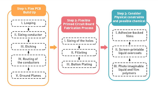
Step 1: Flex PCB Build Up
The base material used for flex boards is polyimide which is costly than the FR-4 material used in rigid boards. So it is wise to use base material carefully, especially if you want to manufacture the circuit boards with lower costs. More often, the nesting technique is used to save polyimide where circuits are placed adjacent to each other. Normally the circuits come with four segments per panel, however, you can make it 16 segments per panel if you employ the nesting technique.
The manufacturing process of the flex circuit boards include:
Service Loop
The service loop is adding a slight amount of extra material more than the designer’s limit to the circuit board. Use service looping if you want to improve the assembly or servicing length of the circuit.
Selecting Copper
It is preferred to pick the thinnest copper to apply remarkable flexibility to the circuit. The thinnest copper comes in handy especially when you intend to use the circuit board for dynamic applications.
Etching
The manufacturing process may lead to isotropic losses. The etching process is used to compensate for those losses. In this process, the copper foil thickness is almost half the line width loss. Line width can be influenced by different factors including different types of copper, equipment, conductor, and etch mask.
Routing
Conductor routing is applied to the specific regions of the circuits to reduce stress and to improve the bending and folding capability of the circuit board.
Ground Planes
Ground planes are created to reduce the overall weight of the circuit board and to improve circuit flexibility.
Step 2: Flexible Circuit Board Fabrication Process
In this step, we’ll further expand on the process that occurred on the circuit boards. First, we’ll discuss conductor spacing and width.
When you’re using polymer thick films then the common conductor width would require 375 micrometers. Nominal polymer thick films come with the ability to carry current. While silver-based thick films, on the other hand, can support 25% of the total circuit current.
In flex boards, the diameters for through holes can vary from 200 to 250 micrometers based on the design and the application.
Hole Size
Manufacturers can create small holes based on the design. With the inception of advanced technology, manufacturers can produce holes as small as 25 micrometers.
Filleting
Filleting is applied on the pads and land termination points to evenly distribute the stress. Plated through-holes are used to create an efficient solder joint.
Button Plating
This method is used to create a substitute plated through-hole where copper is used to creating vias and through-holes.
Step 3: Consider Physical Constraints and Possible Chemical
In this section, we’ll discuss cover layers and cover coating issues. The coverlays are used in flex boards instead of solder mask that is used in rigid boards.
The common cover layers employed in the manufacturing process include:
Adhesive Backed Films
Adhesive-backed films come with balance raw materials, making them a suitable match for dynamic flex circuit applications. The majority of manufacturers use these films for cover coating.
Screen-printable liquid overcoats
It is preferred to use screen-printable liquid overcoats to save cost.
Photo imaginable liquid and film polymers
This method is commonly used for over-coating as it doesn’t show any irregularities as you happen to deal with other cover layers.
The crucial features of this cover layer include:
- This cover layer secures the circuit board from external and internal damages.
- The layer behaves as a solder mask, preventing the solder from circuiting tracks.
- Keeps the circuit board from external electrification.
These are three major steps to manufacture flexible circuit boards. However, they may vary from manufacturer to manufacturer.
Price
Flex circuit boards simplify component assembly and can reduce erratic wiring. They are lightweight and can fit into less space. The cost may vary for different boards based on the three different factors:
Physical size: The physical size of the board does affect the overall cost of the board. The more the size, the more the cost. The flex boards are normally manufactured in rectangular panels. The cost mainly depends on the number of boards you can nest in a panel. The more boards you can incorporate on the panel, the less price you’ll pay per circuit.
Circuit Construction: The number of conductive layers per circuit also defines the cost of the board. The multilayer board would cost more than the standard single-layer flexible board.
Volume: The more the quantity, the lesser the price of the board.
Other important factors that can influence the price of the board include :
- Minimum trace and space
- The thickness of the PCB and Aspect Ratio
- Size of hole
- Custom and Unique Specs The custom specs depend on the application. Like the boards that include rounded edges would need more cost to manufacture. Similarly, if you demand metal edges for your board, the price of the board will increase.
Applications
The need for flexible circuits is increasing, with applications in the simple and advanced electronics sectors including automotive, consumer, electro-medical devices, telecommunications, wearables, and aerospace.
The common flexible PCB applications include:
- Used in dynamic flexing application in which flex boards can be bent several times.
- Used in laptop computers, cell phones, and digital cameras.
- Employed in the medical field like the production of hearing aids, pacemakers, and heart monitors.
- Widely incorporated in processing machines, robotic arms, and bar code equipment.
- Lightweight and an ability to cover less space make these boards a suitable fit for satellite and GPS applications. That’s all for today. Hope you’ve enjoyed reading this article. You can pop your comment in the section below if you’re unsure about anything. I’ll help you out the best way I can. Thank you for reading this article.


Top comments (0)