
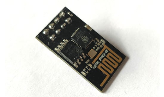
The ESP8266 has a high processing speed on board. This module has a lot of storage space, which lets it function with other gadgets like detectors. Since this PCB lacks an onboard voltage regulator, we must undertake external level shifting to ensure the module could work with other development boards. Because it is an affordable module, it is widely utilized in a variety of applications, including the IoT and many more. So, here, we would go over the essential characteristics of the ESP8266, the pin features, steps involved in programming this PCB, and a test program.
ESP8266 Features
- A 32-bit Tensilica microprocessor, antenna switches, RF balun, power amplifier, regular digital external connections, reduced noise reception amplifier, voltage regulation module, and filter functionality are all included in this SoC.
- The processor operates at 80 MHz and is centered on Tensilica Xtensa Diamond Standard 106Micro.
- It possesses a 64-kilobit boot ROM, an 80-kilobit user data RAM, and a 32-kilobit command RAM.
- It has 16 GPIO, I2C, Serial Peripheral Interface (SPI), 10-bit ADC, and I2S interfaces featuring DMA, as well as Wi-Fi 802.11 b/g/n about 2.4 GHz.
- Peripheral QSPI flash memory could be obtained via SPI and allows up to 16 MiB, with 512 KiB to 4 MiB integrated into the module at first.
- It's a significant advancement in wireless communication with less equipment. The board is powered by an inbuilt regulator that ensures a constant 3.3V supply.
- It is compatible with APSD, making it an excellent solution for VoIP and Bluetooth applications.
PIN Configuration of ESP8266

- Ground: provides ground to the module
- VCC helps in providing voltage of about 3.6 V at maximum
- Rx is for receiving serial data
- Tx is for transferring serial data transfer
- CH_EN is for shutting down the microchip
- RST stands for "reset pin."
- There are 16 GPIO for general use.
Steps for Powering Up the Module
- The USB to Serial converter could be utilized to power the gadget from a Computer port. The gadget may be powered up with 2AA and LIPO batteries.
- It is not recommended utilizing a 5V dev board to power this gadget. This could have a significant impact on the gadget's quality and total functioning.
Programming Of ESP8266
This PCB, like other Arduino development boards, may be programmed with the Arduino IDE. However, in order for the Arduino IDE to identify this board, we must get appropriate libraries and drivers installed. So, first and foremost, we'll walk you through the ESP8266 module installation process in the Arduino IDE.
Instructions For Setting Up The ESP8266 In Arduino IDE:
- The first step is to access the preferences box in your Arduino IDE.
- To access the preferences window, navigate to the File tab in the Arduino IDE's top left corner and then to the 2nd last selection, which is named preferences. You could also use the image above as a guide.
- When you open the preferences window, you would notice something like this.
- The extra board's management URLs, which are marked in the preceding image, are readily visible. You must insert the ESP8266 package link in this URL. When starting the installation process for the ESP8266 package, head out to: http://arduino.esp8266.com/stable/package_esp8266com_index.json and click OK. This option allows us to have many URLs. You could store several URLs by writing numerous URLs and then separating them with a comma after one entire URL.
- After you have finished those steps, head out to the board's manager alternative. To do so, navigate to the Tools tab on the upper tab of the Arduino IDE, which is the fourth choice. Head to the board after opening the tools tab, and you would notice the board manager option.
- You must now look for your desired board. In this situation, it is the ESP8266, so hunt for that and then pick the "ESP8266 platform" to start the installation. If you are still unsure, look at the image below.
- After you've finished with those procedures and everything occurred properly, you would be successful in selecting your ESP8266. Now return to the tool tab and pick the board option, then the generic ESP8266 module.
- You must choose both your PCB and your port. The image below demonstrates this. Admittedly, these methods merely require you to restart your Arduino IDE in order for the modifications we have made to take effect.
Bootloader Modes Of ESP8266
Our bootloader could have a variety of modes based on the conditions of the common goal GPIOs, like 15, 2, and 0, as these modes are reliant on the conditions of the above specified generic intent input/output pins. We're only concerned with flash startup mode and UART download mode in our scenario. We have developed a table that relies on the aforementioned pin to display the pin configuration you must utilize to employ a given download mode.
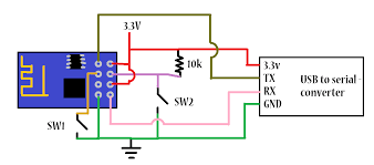
Circuit Diagram For ESP8266 With USB to Serial Converter
The circuit model for linking our ESP8266 board to the PC for programming is shown underneath. All you are required to do now is hit the flash button to start uploading. Certain boards employ the flash and the reset button for this, but this is not the case with this one. So, according to the table, we must link GPIO 0 pin as low, GPIO 2 pin as high, and GPIO 15 pin as low for this purpose. To put our board in serial programming mode, press and hold the reset button, then press and hold the flash button while still holding the reset button.
ESP8266 Projects & Applications
The ESP8266 Wi-Fi module is commonly used in embedded projects and gives Wi-Fi functionality. Here are certain ESP8266 designs and utilization to assist you in getting started:
- Wireless Web Server
- Geolocation with ESP8266
- Pressure Sensors on Railway Tracks
- Air Pollution Meter
- Temperature logging system
- World’s smallest IoT designs
- Wi-Fi regulated robot
- Humidity and temperature monitoring
- M2M with ESP8266
Conclusion
In summary, the ESP8266 module is pre-programmed with AT command set software and could be put into any other development board to operate as a Wi-Fi shield. However, while utilizing it with various development boards, we ought to be careful on the method the ESP8266 receives operational voltage since it is incapable of withstanding over 3.6 V, and the steps involved in building serial connections with other development boards and ping other gadgets.


Top comments (0)