
In the realm of technology, the IoT have been a popular topic. The manner we operate has altered as a result. More than ever before, physical items and the computerized world are linked. With this in consideration, Espressif Systems has introduced the ESP8266, a little, bite-sized Wi-Fi equipped microprocessor, for an attractive deal! It could track and operate items from any part around the globe for lower than $3, making it ideal for almost any Internet of Things application.
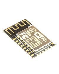
ESP-12E Module
The development board has an ESP-12E module with an ESP8266 microchip with a Tensilica Xtensa® 32-bit LX106 RISC CPU that enables RTOS and runs at 80 to 160 MHz configurable clock frequency.
It possesses about 128 KB of RAM and 4MB of Flash memory (for application and data storage), which is more than adequate to handle the enormous strings that comprise web pages, JSON/XML data, and anything else we hurl at IoT gadgets these present times.
The ESP8266 has an 802.11b/g/n HT40 Wi-Fi transmitter, letting it get connected to a Wi-Fi connection and communicate with the web, as well as create its network for other gadgets to set up connection. It expands the capabilities of the ESP8266 NodeMCU.
Power Requirement
The PCB has an Low-dropout voltage controller to maintain the voltage stable at 3.3V, while the ESP8266's operational voltage range is 3V to 3.6V. Whenever the ESP8266 draws about 80mA throughout RF broadcasts, it could dependably provide about 600mA, that would have been completely sufficient. The regulator's output is likewise separated off to one of the boardPCB's sides and designated as 3V3. Power can be supplied to peripheral devices through this pin.
The on-board MicroB USB connection provides energy to the ESP8266 NodeMCU. Suppose you possess a controlled 5V voltage provider, you may utilize the VIN pin to power the ESP8266 and its accessories remotely.
Peripherals and I/O
The ESP8266 NodeMCU includes 17 GPIO pins on either side of the PCB, which are split off to pin headers. These pins may be utilized for a variety of different tasks, like:
- A 10-bit Analog to Digital Converter channel is referred to as an ADC channel.
- UART interface: The UART interface is utilized for serially loading codes.
- PWM outputs: To regulate motors or lower LEDs. SPI, I2C, and I2S interfaces: For connecting numerous detectors and peripherals.
- Suppose you're planning to include sound to your work, use the I2S interface.
- The ESP8266's pin multiplexer functionality comes in handy. This means that a particular GPIO pin may be used for PWM, UART, or SPI.
On-board Switches & LED Indicator
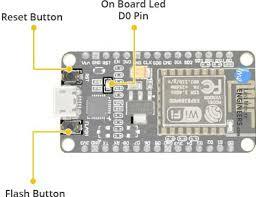
There are 2 buttons on the ESP8266 NodeMCU V3. The Reset button, labeled RST and placed in the upper left corner, is utilized for resetting the ESP8266 microchip.The PCB's download button is located in the bottom left corner and is utilized for upgrading firmware.
A customer Light Emitting Diode indication is also included on the PCB, that is coupled to the D0 pin.
Serial Communication
The board contains a Silicon Labs CP2102 USB-to-UART Bridge Controller, that transforms USB signals to serial and lets you start programming and connecting with the ESP8266 microchip from your PC.
Suppose you possess an earlier variant of the CP2102 driver on your computer, we urge that you update it right away.
ESP8266 NodeMCU Pinout
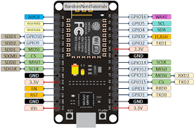
The ESP8266 NodeMCU seems to have 30 pins which allow it to communicate with the rest of the world. The following are the links:
- Power Pins: It consists of a voltage input pin and 3.3V output pins that are a total of three. Suppose you possess a controlled 5V power source, you may utilize the VIN pin to immediately feed the ESP8266 as well as its accessories. The 3.3V pins like earlier stated are output pins of a voltage regulator on the board. Power could be supplied to peripheral devices through these pins.
- GND: It is the ESP8266 NodeMCU's ground pin.
- I2C Pins: These are utilized in connecting your program's I2C detectors and accessories. Inter Integrated Circuit Master and Slave are enabled. Inter Integrated Circuit interface capability may be implemented automatically, with a maximal clock frequency of 100 kHz. It ought to be remembered that Inter Integrated Circuit clock frequency must be greater than the slave gadget's weakest clock frequency.
- GPIO Pins: The ESP8266 NodeMCU includes 17 General Pin Input and Output pins that may be dynamically allocated to different tasks including Inter Integrated Circuit, Internet Information Services, Universal Asynchronous Receiver Transmitter, Pulse Width Modulation, Button, IR Remote Control, and Light Emitting Diode Light. Every digitally equipped GPIO may be tuned to higher voltage or internally pulled up or down. It may also be modified to edge or level-trigger to create CPU interruptions whenever it is set up as an input.
- ADC Channel: ESP8266 has a ten-bit SAR ADC built in. Evaluating VDD3P3 pin’s DC power supply and the TOUT pin’s inputted voltage are two roles that may be done utilizing ADC. Both are unable to get implemented simultaneously.
- Pulse Width Modulation Pins: The PCB features four PWM channels. Its output may be dynamically integrated and utilized to drive digitized motors and Light Emitting Diodes. Its range is configurable among both 1000 and 10000 seconds.
Conclusion
The ESP8266 may be programmed using a number of different development frameworks. You could utilize Espruino – a JavaScript SDK and firmware that strongly resembles Node.js, Mongoose OS – an IoT OS, or an Espressif SDK).


Top comments (0)