
This tutorial was originally published here
(If this is your first time here, check out my first MicroPython tutorial. Use it to get acquainted with the Wokwi simulator interface so that you are prepared to dive into this tutorial)
Knobs are a universal way of controlling devices - you use them on stoves to control the temperature, on speakers to control the volume, and on Russian spacecraft to control...space stuff. The point is, they're charming and an absolute joy to use. But have you ever wondered how they work? How do these devices know how far you've turned the knob?
 The Soyuz spacecraft's control panel. A thing of beauty. Mostly because of the knobs. (Stanislav Kozlovskiy, CC BY-SA 4.0, via Wikimedia Commons)
The secret lies in a little component called the potentiometer. A potentiometer is a rotatable device whose output voltage is a fraction of its supply voltage. That fraction depends on how far you've rotated it. Aha! If we measure this output voltage, we'll know the fraction and we can use that to back-calculate how far the potentiometer/knob has been rotated. But how do we measure the output voltage from the potentiometer?
In all digital electronics, voltage is measured using an ADC, or analog-to-digital converter. Voltage is considered 'analog' because it's a real-world physical quantity. It is the ADC's job is to measure that and convert it into a number that a microcontroller, such as our Raspberry Pi Pico, can understand. Luckily for us, the Raspberry Pi Pico comes with 3 ADC pins built-in! We can measure voltages to our hearts' delight. The 3 ADC pins are on the right side of the Pico as shown in the pinout diagram.
 The ADC pins are available on pin GP26, GP27 and GP28
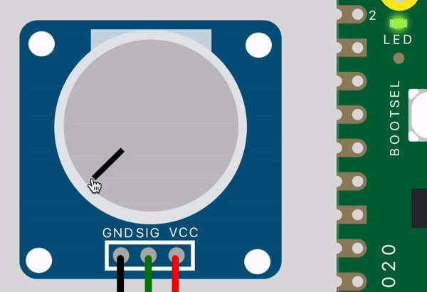
Without further ado, let's get into it! Fire up a new MicroPython project in the Wokwi simulator, click the 'plus' button at the top of the simulator, and select the Potentiometer component. You'll notice that it has 3 pins: GND, VCC and SIG. These correspond to ground voltage, power supply voltage, and the signal voltage representing the amount of rotation, respectively.
 GND, SIG and VCC pins on the potentiometer
Let's connect them up! Connect GND to any ground pin on the Pico - I chose pin 18 at the bottom-left. Connect VCC to the 3.3V output pin, which is pin 36 at the top-right. Lastly, wire up the SIG pin to one of the ADC pins - I connected mine to ADC0 which is at pin GP26 on the right. After wiring, your setup should look similar to this:
 Potentiometer connected up to the Pico in the simulator pane
Before we write the code, there's something you should know about ADCs. I mentioned earlier that it converts the voltage into "a number" for the microcontroller to use. However, that number is not the voltage itself. For example if the voltage is 2.2V, the ADC will not directly report "2.2" to the microcontroller. In the Pico's case, it will actually report the number "43690".
Huh? Why 43690? Why is technology always so confusing? Fret not, there is an explanation. The ADC on the Pico is a 16-bit ADC, i.e. it has a numerical resolution of 16 bits. In simple terms, this means that it reports values from 0 at the minimum to (2^16 - 1), or 65535, at the maximum. An input voltage of 0V would correspond to an output value 0, and an input voltage of 3.3V would correspond to an output value of 65535. Any voltage in between corresponds linearly to a point between these two extremes. Let's visualize this with a graph.
 Plot of reported ADC value vs voltage on the Pi Pico's ADC
The relationship between the voltage seen by the ADC and the value it reports is linear. With that graph, it's clearer now why 2.2V corresponds to a reported value of 43690 on the Pico. If you would like to calculate that number instead of meticulously drawing a graph and finding the value by hand, there is a simple formula to convert voltage to ADC value.
ADC value = Voltage * 65535 / 3.3
Now that we know the ADC reports 16-bit numbers to represent the voltage, we are ready to write some MicroPython and read the values from the potentiometer. We are going to use our trusty machine and time libraries to read the ADC value and to set the rate at which we read it. Type the code below into your Wokwi editor.
 Code for reading the ADC on the Pico
In the first two lines we import the necessary libraries. We then set up pin GP26 as an ADC. Next we start the infinite loop where we read the 16-bit value from the ADC pin, print out this value in the console window, and sleep the Pico for 0.1 seconds. Let's run the simulation and play with the knob to see it in action! Press the 'play' button at the top of the simulator pane and use your mouse to rotate the potentiometer.
 Turn it up to 11! I mean, 65535! Doesn't quite roll off the tongue 😐
If you were expecting that to be as satisfying as turning a real physical knob, I'm sorry to disappoint. Maybe this is how future generations will feel when turning knobs in their virtual reality metaverse.
So far we've learned how to read the ADC, but we're not done yet. The real fun is in actually controlling things with the potentiometer. In our last tutorial, we wrote a program to blink the LED onboard the Pico every 0.5 seconds. But what if we want to change that number to make the LED blink faster or slower? We can use the potentiometer! The LED onboard the Pico is connected to pin GP25 - let's write a program to blink that LED, and use the knob to control its blink rate. This flowchart helps to visualize the program.
 Flowchart for controlling the LED blink rate using the potentiometer
We are almost ready to write the code. We're just missing a way to convert the ADC value to a time delay. We need to set a minimum and maximum time delay and map that to the minimum and maximum ADC values, 0 and 65535. To keep it very simple, let's have a minimum delay of 0.1 seconds and a maximum of 1.1 seconds. The formula for this is:
Time delay, td = 0.1 + knob_value / 65535
Let's modify our previous code to match the flowchart. The final code should look like this:
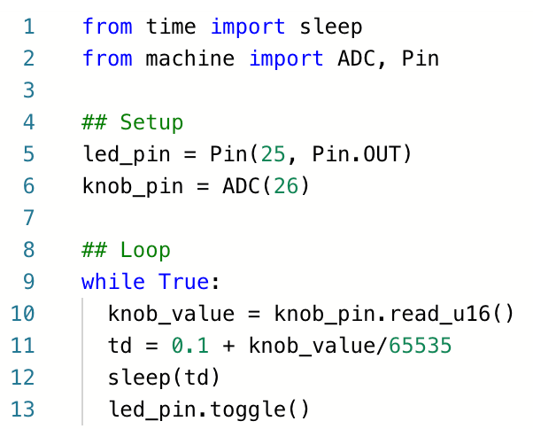 Code for controlling the LED blink rate using the potentiometer
Run your code by pressing the 'play' button in the simulator. Twist the knob and enjoy the incredible feeling of controlling our little green LED.
 Now if only I had to knob to control my heartbeat like that
That's it! Play with the code and see what interesting directions you can take this project in. As a small exercise, try reversing the logic so that the LED blinks faster (instead of slower) when you turn the knob up. Good luck, and comment below or message me for any questions :)
Next time in Secrets of MicroPython, we will use our new knowledge of ADCs to read data from a temperature sensor. Follow me to be notified when the next tutorial is out. Stay tuned!
This tutorial was originally published here

Top comments (0)