
(Note: these posts are migrated from my previous medium.com blog)
I’m a big fan of Lego, especially the Technic series. Some of these sets come with Power Functions, which adds motors/servos/lights to the model and lets you control them with an IR remote:

2 of my favourite, the excavator and the Mercedes Benz Arocs

Lego Power Functions
Not all sets come with a remote, and for each channel you would need an IR receiver; wouldn’t it be cool if you could control everything with your phone over Bluetooth?
Power Functions: How Do They Work?
All Lego Power Function connectors have 4 wires; 2 of them carry the +/- 9V from the battery box, while the other 2 provide direction and speed control:
](https://res.cloudinary.com/practicaldev/image/fetch/s--EHIxsift--/c_limit%2Cf_auto%2Cfl_progressive%2Cq_auto%2Cw_880/https://cdn-images-1.medium.com/max/2000/0%2A8T6eAl0Fmz6O47Kx.jpg)
The wires C1 & C2 allows you to control to the motors/servos/lights. Drive one of the wires with PWM and the other at ground to control the speed; swapping the input reverses the direction. A great resource to learn more about the Power Function actuators can be found here: http://www.philohome.com/tech.htm
Concept Diagram

There are 3 main components to this build:
A Bluetooth module for sending/receiving commands
An Arduino to interpret those commands and output PWM signals
A motor controller that can provide enough current to drive the actuators
I would normally just wire all of these components together and call it a day, but this time I wanted a cleaner solution and try creating my own PCB…
PCB Design and Fabrication
Our build is simple enough that you could hand wire everything and be done with it, but where’s the fun in that? Designing your own PCB is a great learning experience that can be both fun and rewarding; it will also help you down the road as you try to tackle more sophisticated projects. There are quite a few free tools out there that let’s you do that now (e.g. KiCad, Eagle, EasyEDA, Upverter, etc.), with tons of online resources to learn how.
I won’t go into details on how to use these tools in this post (YouTube is your friend), but the first step is to turn the concept diagram into a schematic and choosing the right components:

For the main Arduino controller, I chose the Arduino Pro Micro as I have a few of those around. It also has the right number of GPIO pins we need in a small form factor. I chose the 3.3V variation as our Bluetooth module runs on 2.7V — 3.3V.
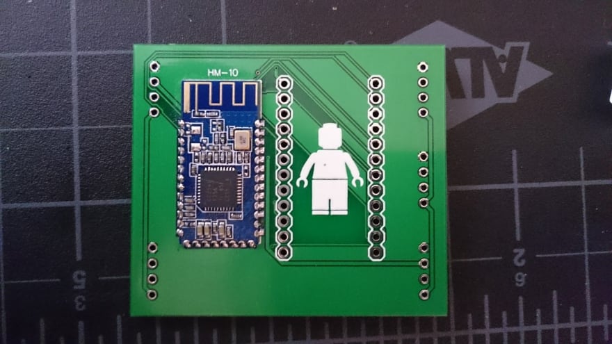
For the Bluetooth LE module, I chose the HM-10; it’s based on the CC2541 and can be found for a few dollars on eBay. It has a simple UART interface that simply passes through any data you send to it via its custom Service & Characteristic.
For the motor controllers I chose the TB6612FNG from Toshiba. I originally wanted to use the popular L298N as it’s capable of driving more current. Unfortunately, it is commonly found in the Multiwatt15 package, which is too big for my desired form factor. Each TB6612FNG IC can drive 2 channels, so we’ll need 2 of them total. I also threw in some decoupling capacitors to reduce noise (10uF electrolytic and 0.1uF tantalum).
Last but not least, we’ll need 4 pin connectors for the Power Function Lego connectors. We could have soldered the wires directly to the board, but I wanted to keep things modular (plus connectors look nicer). I chose the popular JST XH connectors.
All the above components can be found on DigiKey or eBay. I always order extras in case I mess up the soldering (or when I lose those super tiny SMD components).
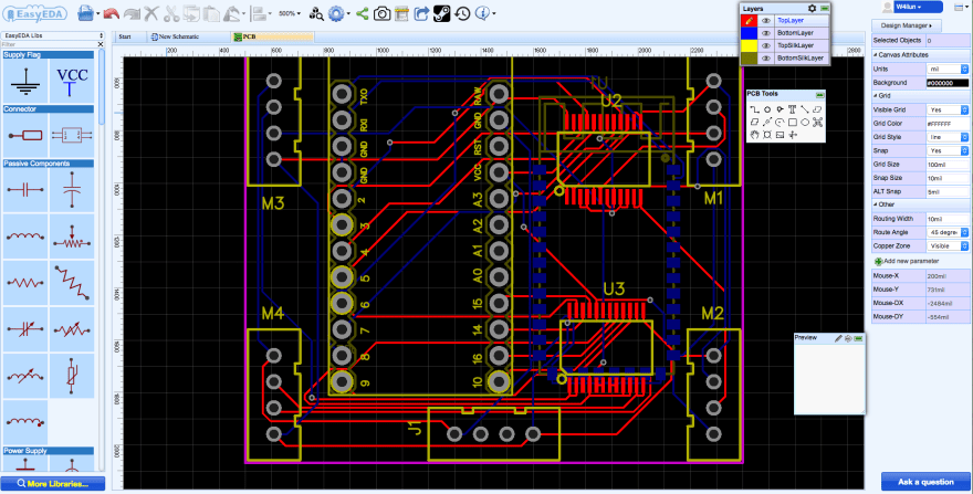
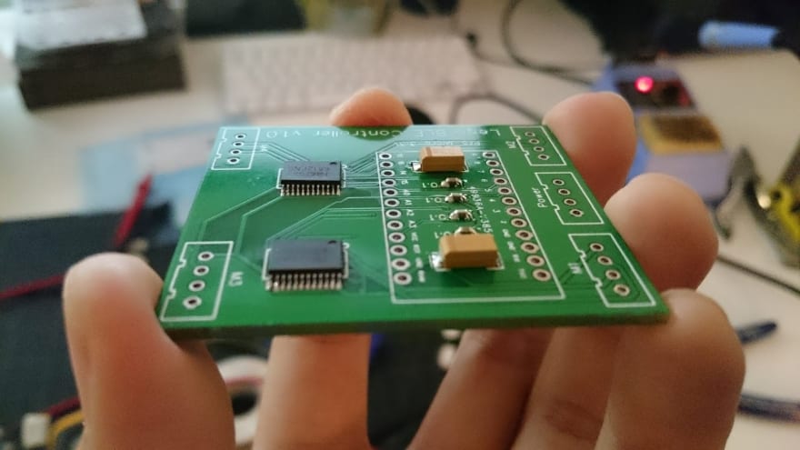
The next step is to convert your schematic into a board layout. I chose a 2 layer design and placed the components strategically around the board. The Pro Micro, motor controllers, and connectors go on the top for easy access, while the Bluetooth module goes on the bottom to save space. I also used the auto-route feature so you don’t have to do the routing yourself; I do find, however, that routing your traces manually yields cleaner results. The screenshot above was my first iteration of the design.
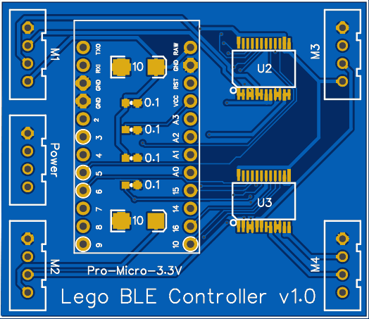
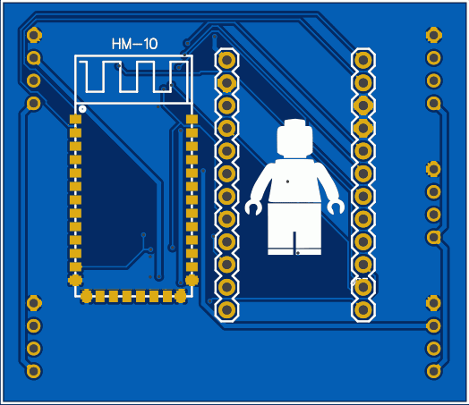
Once you are happy with your board layout, you can generate a render of your board. It is a great visual check for any outstanding issues (and it also lets you play around with the design, like adding a Lego man to the silkscreen).
The final step is to generate Gerber files from your design, and sending it off to PCB fabs! Gerber files are the standard for PCB manufacturing, and they serve as instructions for creating the board (e.g. layout, top/bottom silkscreen, drill holes, vias, etc.); think of it as gcode in 3D printing. There are tons of PCB fabs out there but my favourite is OSHpark; they offer quick turnaround times and they also accept KiCAD/Eagle project files, this means you won’t have to generate/convert Gerber files with them and can directly upload your project.
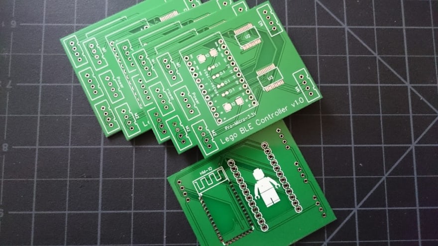
My boards came in 2 weeks after I sent in the designs. I wanted to get a blue PCB like my render, but that costed $10 more :( You can find all of the design files on my GitHub https://github.com/w4ilun/lego-ble-controller/tree/master/hardware
Board Assembly

We only have a few SMD components but they can be tricky to solder if you don’t have steady hands. I used Kester flux and ‘drag soldered’ the SMD components, then did all of the through hole components. An easier alternative would be to use solder paste and put the whole thing in a reflow oven.

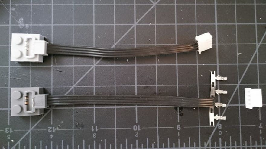
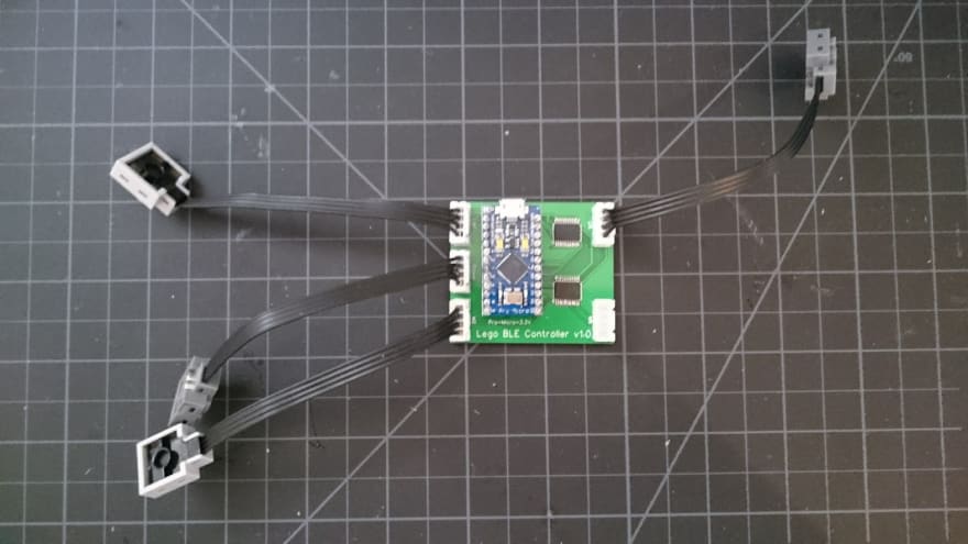
You will also need to attach the Lego extension wires to your 4 pin connectors. Make sure you have them in the right orientation by referring to the schematic. You could also solder the extension wires directly to the board without the connectors.
Firmware
The firmware is very basic: read some input string from the serial port and turn on/off the appropriate pins accordingly. Every channel requires 3 GPIO pins to control its direction and speed:

You can find the pin number mappings in the schematic; the code snippet below shows how to turn the motor in one direction at half speed:
digitalWrite(m1en1, HIGH); //CW or CCW
digitalWrite(m1en2, LOW);
analogWrite(m1pwm, 128); //values can be 0-255
For the command protocol, it is simply a string of 4 integer values separated by a #. For example, **128#-255#10#0 **means drive Channel 1 at ~50%, drive Channel 2 at full speed in reverse, drive Channel 3 at 10/255 speed (~4% of max), and brake Channel 4. If a channel is connected to a Lego servo, -255 represents -90 degrees, 0 is center, and 255 represents +90 degrees. Unlike a regular hobby servo, the Lego servo only has 7 steps in each direction, so intermediate values between that range will be ignored (you can learn more about the Lego servo in this YouTube video.
All together, the firmware is simply an infinite loop that waits for commands from the Bluetooth module via serial, then sets the motor direction and speed for each channel. You can find the firmware code on my GitHub https://github.com/w4ilun/lego-ble-controller/tree/master/firmware
Web Bluetooth App
To control our Lego Power Function motors/servos/lights, we will need to talk to our Bluetooth LE module some how. We can create a native mobile app for iOS/Android, or use one of the Bluetooth LE APIs in Python or Node.JS (such as Bleno by @sandeepmistry).
For this project, I’ve decided to leverage the cutting edge Web Bluetooth APIs available in Chrome 45+. You will need to first enable this experimental feature under chrome://flags (though this feature is enabled by default in Chrome 56+)
The cool thing about Web Bluetooth is that it works right from your browser, without needing additional libraries/plugins! It works on both desktop and Android, and you don’t need to download anything extra; simply visit a web page that has Web Bluetooth enabled and you’re presented with option to interact with nearby Bluetooth LE devices. The JavaScript snippet below shows how you can discover devices, connect, discover services/characteristics, and reading/writing to them:
navigator.bluetooth.requestDevice({ filters: [{ services: [service] }] })
    .then(device => device.gatt.connect())
    .then(server => server.getPrimaryService(service))
    .then(service => service.getCharacteristic(characteristic))
    .then(characteristic => {
        characteristicInstance = characteristic;
    setInterval(updateSpeed,200); //send commands every 200ms
    return characteristic.writeValue(str2ab("0#0#0#0"));
    })
.catch(error => { console.log(error); });
The complete code can be found here https://github.com/w4ilun/lego-ble-controller/blob/master/index.html; I’ve also enabled GitHub pages on my repo, so if you built the same controller as I have, you could simply go to https://w4ilun.github.io/lego-ble-controller/ and start controlling your Lego!

I only created 2 control channels in this interface for testing; to expand on this example, you can add additional UI elements (such as toggle buttons, dials, etc.) and simply map them to the command string (CH1#CH2#CH3#CH4, right now CH3 and CH4 default to 0). You can also use your phone’s accelerometer data as input (e.g. deviceorientation ).
Trying It Out

I put together a “car” to test out everything and much to my delight, everything worked perfectly :)
This learning experience has been a lot of fun and I look forward to improving on this design. In the next iteration I plan to consolidate the Bluetooth LE module and the main microcontroller, and not use the Pro Micro + HM-10 (ESP32 perhaps?).
You can find everything you need on my GitHub; I still have a few extra PCBs so feel free to reach out and I’d be glad to send you one to try for yourself.
Enjoy!


Latest comments (0)