
This post was originally posted on https://blog.bajonczak.com/ some links to images may break.
The Hive Monitoring project
I'm working permanently at apiary at the bees. In the summer it is very time consuming. Since I figured out that I can use IOT for some monitoring tasks.
These includes measures like
- the Weight of the hive
- the Temperature of the hive
- the Humidity of the hive
- the position of the hive (for protection against theft)
With this information it is for me possible to identify when it is the best Time to harvest the delicious honey. To warn me when a bee colony will swarming out, or to identify at the winter time, how many food the bees got in the hive.
To get the data I can use a normal scale for a person, a wireless temperature sensor and put it in and below the hive.
But this solution is not very comfortable and handy. Because I must go out every time and check the values from the devices.
But I want an IOT Way. So I started to tinker s.th. with an ESP8266 controller.
The Components
To realise this project I set some main goals
- The System must work with wireless connection
- The System must work with Solar Power
- The System must Measure the weight
- The System must Measure the temperature
So first I figured out a well suited device. That meets the criteria above.
Finally I figured out that Wemos D1 Mini is well suited for the requirements above. Because it has an wireless module on board. But I want that the device will be powered by a solar module. For that there exist a special HUZZAH version. This is designed for the use of a battery.
On this module we can attach several devices, because it has some GPIO Ports. These ports are connectors on that we can mount the cables from the sensors.
Now my requirement list looks like this:
- ✔ The System must work with wireless connection
- ✔ The System must work with Solar Power
- The System must Measure the weight
- The System must Measure the temperature
The Sensors
Now I must find the required sensors, to measuring the weights and temperature of a hive.
Weight Sensor
For weighting the hive I must use a sensor called Load cell. For my requirement this load cell must support weights about 200 Kg. After a little search I found the H30A load cell.
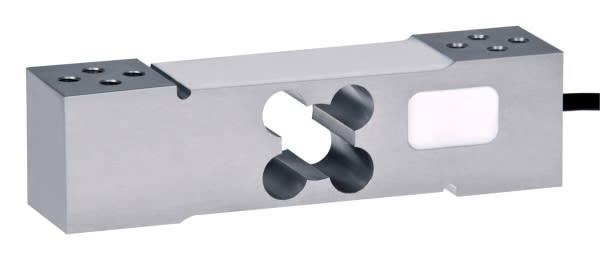
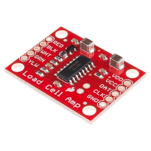
Now I got a device that can weight a hive... but wait there is one part missing... Because the load cell works with analog values, because the cell is like a resistor. To translate this analog values to digital values we need a translate module. For this there exists the breakout chip HX711
To measure the weight of the hive I must construct a small platform so that I can place the hive on top of the weight cell.
For this I use two L-profiles with aluminum and screws to mount all together.
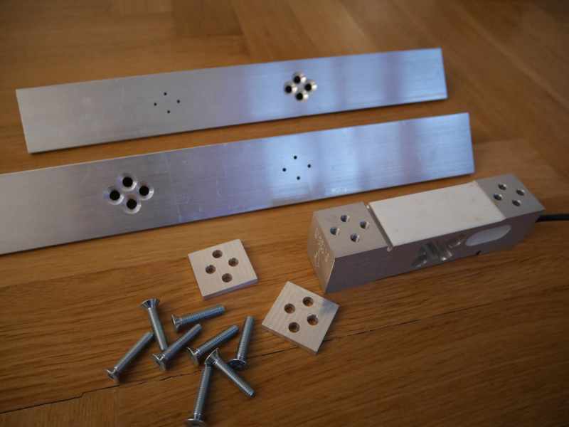
to get the right position of the drilling holes I use a template. So the completed construction looks like this
This design I call scalebar. This measures the weight only from one half of the hive. So i simply multiplicate the measuring by two to get the total weight. There exist another construction design, but I am not very talented in welding metal :).
Perfect, now my bullet list looks like this:
- ✔ The System must work with wireless connection
- ✔ The System must work with Solar Power
- ✔ The System must Measure the weight
- The System must Measure the temperature
Temperature Sensor
For measuring the temperature the most commonly used device is the DHT.
But this device has some disadvantages to use it in a hive. Because the bees will construct the honeycombs about this device. Then the small holes on this device, to get the temperatures, will be closed. in the end it is not possible to measure the correct temperature inside the hive.
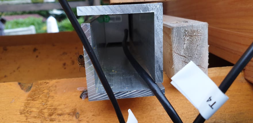
Instead of using the DHT-device I can use a more closed device. After a little research I find the ds18b20- Temperature sensor. This is a small transistor, but there is an encapsulated one like this:
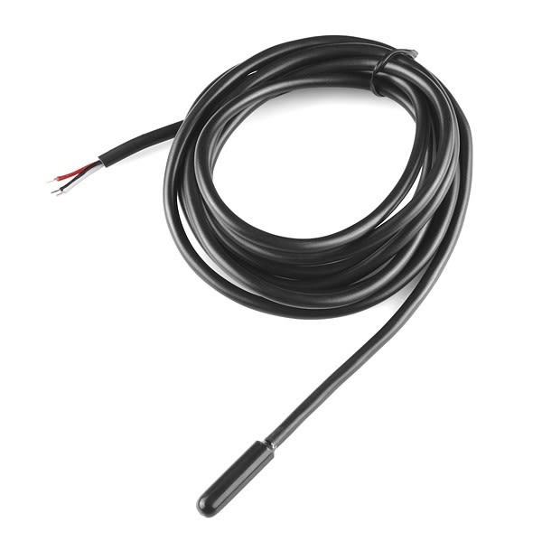
This device is well suited for my requirements becaus I can hang in this to the
- ✔ The System must work with wireless connection
- ✔ The System must work with Solar Power
- ✔ The System must Measure the weight
- ✔ The System must Measure the temperature
Yes my bullet list is now complete. So I wiring up the things now.
Powering
Stop before we wiring up the components together I will stop for now on the powering topic. Because a battery don't have an unlimited power capacity. So I decided to use a solar cell for loading the battery on a sunny day.
So the final design is for now that the battery works as a puffer battery and the solar module is loading the battery over the day. But the Device will be powered within the battery power. This helps me to get a constant power supply.
But I cannot wiring the cables from the solar modules to the battery and then the same cable to the module. With this wiring the following problems comes up:
- No stable power supply
- Over discharging of the battery can occur (memory effect)
- Overcharging the battery on a very sunny day (battery will be damaged)
So what now?
Thankfully there exists a module that supports a linear charging of a battery by a solar module CN3065. I ordered mine on Ebay.
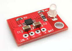
This solar charger module supports an input connector for the solar cell and an output connector for the battery. From this cables I can also connect the device too.
Perfect, in theory I can now measure the weight, temperature, power the device by the battery and it will be charged by a solar cell. So it work at least without a power supply.
Wiring
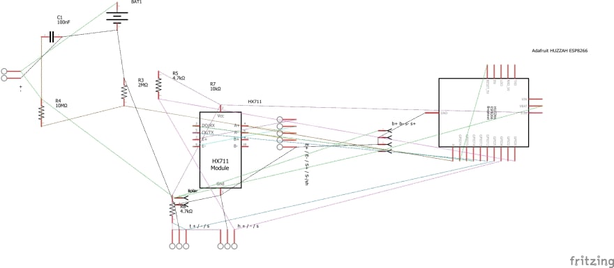
Now the time comes up to bring all things together. Fir this I created a small diagram with Fritzing.
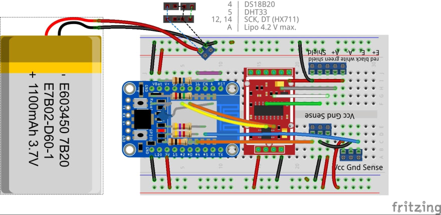
So I added more parts like resistors and capacitors and so on:
For those they want a Buying list Take this :):
| Part | Title | Quantity |
|---|---|---|
| 2M | R3 | 1 |
| 10M | R4 | 1 |
| 4.7K | R5; R6 | 1 |
| 100nF | C1 | 1 |
| HX711 | 1 | |
| CN3065 | 1 | |
| WEMOS D1 Mini HUZZAH | 1 | |
| Lipo 3.7V 1100mAh | 1 |
You will se that the CN3065 will not shown up in the Breadboard and schematic design. This is because that this design is the first draft, that use only the battery. So soldered the Breakout to the wires and it hangs around in the Case now. This is not a problem for me, because it will never gets an short circuit or so.
Also you will notice that there exists som resistors that will attached to the power circuit to the Wemos D1 Mini board. This is a special circuit, to measure the battery capacity. Becaus I will measure this too, to get informed about the battery capacity.
Conclusion
I will stop here for now, because this post will be takes so long otherwise. So I decided to post next time about the software I used and how I created the infrastructure that receives the telemetry data.
Please leave a comment below for suggestions and leave me a feedback.

Oldest comments (0)