Originally published on Medium - 2019-01-17
When I began my journey learning to code at the Flatiron School I had many “WOW” moments. As I successively learned more complicated topics, I became more and more impressed by the amount of work going on under the hood. How was the computer reading my instructions? I knew that knowing as much as I could about how a computer processes my instructions could only help me understand how to help the computer understand my instructions. I became particularly fascinated with logical comparisons and the logic gates that were operating based on my code input. I wanted to take some time to explore how the underlying logic gates supporting programming languages, work.
At the lowest level, most computers function using binary. 0’s that signify off and 1’s that signify on. While it is possible to build computers with more than these two states, it is not practical. Electrical interference or low battery can interfere with the electrical signals that are being processed by your computer. With a simple “yes” or “no, or “on” and “off” the computer has two distinct states instead of 4 or 5 closer states. This helps to guarantee an output of correct results.
From here, a simple transistor is built with two electrodes and a control wire. Here the control wire is the input and the bottom electrode is the output.
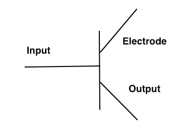
Simple Transistor Gate
When the current flows through the top electrode, it must receive the connecting electrical current from the input in order to send the electrical current to the output.
This would be like if your friend gave you a key to their apartment. Your friend would be the electrode and the key is the input. Without the key, you will not achieve your goal of getting to the output; getting inside your friend's house and eating all of their hot Cheetos.
But this is not enough…
This will only yield a “true” result if “true”, and a “false” result if “false”.
To evaluate more complex logic puzzles, we have 7 common logic gate structures, but they can all be built using a base set of three: NOT, AND, and OR.
The Main Three
Not Gate
If the connection to the electrode is NOT made, then you run the conditional. Otherwise, you don’t run the conditional.
When we put the output wire at the beginning of the transistor and turn the input wire on, the output wire will never receive the current because the input is connecting the two electrodes. Then, once we turn the input wire off, the output wire receives the current, making that conditional true.
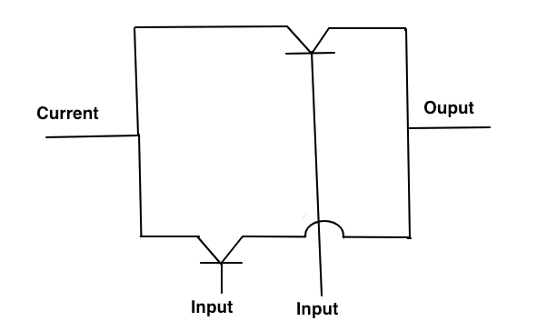
And Gate

Takes two inputs, but has a single output.
When the current passes through the first gate it must be true or else the conditions fail. If the current manages to get to the second gate and the second gate is false, the current will never reach the output. This would make the condition false. If both conditions are true, the electrical current will travel all the way to the output and return the conditional, true.
This is why in programming languages like Ruby and Javascript, you can immediately return from the conditional statement. If the first condition is false, the second one doesn’t matter, the condition will always return false.
Or Gate
A current flows to two separated transistors that are not directly connected to each other. If the current is able to flow through either of these gates, the output will be reached and the electrical current connected. This will run the condition. If both do not connect the electrical current to the output, the condition will not run.
These 3 gates allow us to create 4 other gates. NAND, NOR,
EOR, and ENOR gates. I challenge you to look them up and explore their functionality. It’ll only help you deepen your understanding of the computer languages!

Top comments (0)