
This post is the part 5 of the "Building networks from A to Z" series, please read the 4 previous parts so that you can understand this one. Thanks very much 😁
Before beginning this post, I would like to warn you, routing is a big chapter of networking and this will be a long post, as you're being used to now in this series. I will try to illustrate as much as possible every concept that we will be talking about to make the reading lighter.
Local and foreign networks
In the last part, we spoke about the concepts of networks and netmasks, but we don't know yet how to identify if an host is part of the local network or not.
To do so, you must obviously know the netmask and the address of your local network, and also the IP address that you want to analyze.
As an example, our PC is part of the 192.168.0.0/24 network (which means that the netmask is 255.255.255.0) and we want to know if the 10.23.4.129 host belongs to our network. Just follow this little operation :
         10.23.4.129
AND (&)  255.255.255.0
         -------------
         10.23.4.0
AND bit-by-bit operation just copies both 1 values in the result, as we are talking of a basic netmask here, I just copied the bytes where the corresponding byte of the netmask is equal to 255 (because it is 1111 1111 in binary). Of course, with more complex netmasks, you would have to do the bit-by-bit computing.
For the 10.23.4.129 host to be in our local network, the computation result is supposed to be 192.168.0.0, which it is not. Then this host does not belong to our local network, which means that it is a host from a foreign network. This notion is very important because it will decide whether or not we should route trafic based on the destination IP address. This is the very base of the routing process.
Before talking of routing, I would like to go further and present to you the first network service of the series, Address Resolution Protocol (also known as ARP), which is an application (layer 7) that will intervene between OSI layer 2 and OSI layer 3.
Address Resolution Protocol
In order to send data to a computer, you must know both its IP address and its MAC address, when discussing over the Internet. Internet Protocol apart, you must at least know the MAC address which is required to choose the physical path to which send the data.
ARP has been created in order to solve this problem. Imagine that we want to send a request to a specific IP address, and we know (after doing the calculations shown in part 2!) that the host is in our local network, so we just have to determine its MAC address.
For that specific role, ARP links a specific IP address to a specific MAC address. To know the MAC address of an host identified by an IP address, we just have to do a little ARP request.
ARP requests are sent via the MAC broadcast address (ff:ff:ff:ff:ff:ff, which means that the message is sent to all local hosts) asking Who has [IP address] ?, then the host who effectively has this IP address answers with saying [IP address] is at [MAC address].
After seeing ARP request and associated response, all hosts seeing the dialog are copying the pair of addresses into their ARP table (or cache), which they will be using to send data to each other without asking again.
Here is an example of the ARP process :

Now you know how computers do to know to which IP address corresponds which MAC address. They use ARP !
Fun fact : You can see your ARP table by running the command arp -a (both in Windows - using cmd or PowerShell, GNU+Linux and macOS). Run arp --help to know more about ARP and also to add, remove and update the entries of your ARP table 👀
On the previous post, I wrote that we lack of IP addresses and that, then, the network engineers had to find a way to avoid switching the protocol version (because of the cost of the operation). We spoke about VLSM and having subnetworks, but there is another solution that has been adopted that's called NAT (Network Address Translation).
Network Address Translation
We saw, on the previous posts, that there are some reserved networks, and some of them are reserved to what's called private networks.
Private networks are not routed through the Internet, it is impossible to have a host on the Internet with a private IP address.
Private networks are the following :
- 10.0.0.0/8
- 172.16.0.0/12
- 192.168.0.0/16
If we think, to avoid having too much hosts compared to the pool of IP addresses, we can only address them using private networks addresses and have the messages relayed to them using the "translator", that has both a private IP address and a public one (= an address that is valid on the Internet).
Here is a little diagram with NAT working between a local network and the Internet :

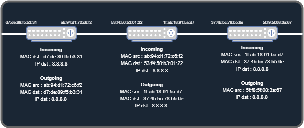
Another basic concept of routing is that, when the computer has to send data to a foreign IP host, it sends it to the gateway (generally, the router, here, the translator), that will try to find the path to the host. Note that only the MAC address is modified to be the gateway's, so that the gateway can still read the destination IP address and route it until finding it, each time we will pass through a router, the MAC source/destination addresses will be changed to fit the router ones. It is a good demonstration that we can not use MAC to route data, because it is needed for electronical pathfinding and IP is an abstraction that allows us to find hosts throughout the Internet !
A transit network is a network in which data just goes to one edge-router to another edge-router. The concept of edge-routers will be explained later in that post.
The translator IS NOT a router, it just edits the source IP address so that the foreign host can answer to him. The translator remembers the first query and its source/destination addresses, when it sees a response from the previous destination address, it basically changes the destination address from the response (which is its own IP public address) to the local host that first emitted the query.
This is it for what is called NAT. 2nd fun fact of this post, the routers you have at home are not actual routers, they are just translators for your local network into the Internet. In fact, your home "router" has a gateway that is a router, on the ISP network. But we will be wondering how the ISPs networks work on the latest posts of this series.
Routing information through the Internet
The routing process is extremely varied, we have a lot of routing protocols that all have a specific goal, but before that, we will see that we have 2 types of routing :
- Static routing : when you say specifically where to find the host, for example, to find host
8.8.8.8, pass through the local router192.168.0.24. Each path is entered manually into the router, which means that we have to know and configure every network on the routing table. We will not be discussing this method that much, this description is quite self explanatory. - Dynamic routing : you just tell the routers what are the connected networks (which means the networks that the router is directly connected to, via cables) to route and it will spread the information to the edge routers (= the other routers in its local network). Here is a simple scheme :
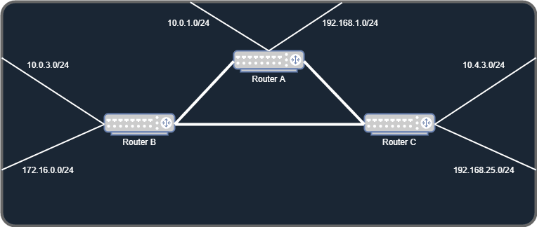
Router A has been configured in the 2 networks it is connected to, and knows that they are here, so it tells Router B and C that the networks are behind him.
If a host from the network 10.0.3.0/24 wants to speak to a machine in the network 10.0.1.0/24, it sends the data to Router B that knows that this network is behind Router A, then it sends the data to Router A by changing the MAC layer as seen before. Router A just switches the query to the host in question.
Router B and C also tell Router A their networks, so that all networks on the diagram are accessible from every host connected to them.
In this case, we can see that we have at least 2 ways to go from a network to another, because the 3 routers are inter-connected in such a way that we have a redundant cable. Each possibility of connecting two networks together is called a path, and it is the main difference between routing protocols, which we will see just after.
The link between Router B and Router C can be removed and the networks from Router C could still be available from Router B. Yes, by passing through Router A, but going through Router A is longer than directly between Router B and C. That is called "cost" and it is a protocol-specific metric.
Here are 2 basic protocols that have been used for decades :
- RIP (Routing Information Protocol)
- OSPF (Open Shortest Path First)
RIP has been declined into two different major versions,
RIPv1 and RIPv2. RIPv1 is classful, meaning that routing was done with specific netmasks defined by each class, whereas RIPv2 is classless, meaning that you could specify, for each network, a specific netmask, so RIPv2 also supports subnetworking.
RIP is a very simple routing protocol, it will just count the number of hops between 2 networks. Let's apply the computation to our diagram above.
10.0.3.0/24 -> Router B -> Router C -> 10.4.3.0/24 - Hops : 0 (direct connection from router-to-router)
10.0.3.0/24 -> Router A -> Router B -> Router C -> 10.4.3.0/24 - Hops : 1 (through Router A)
In RIP, the cost metric is calculated based on the number of hops between two networks, as you can see, for the route 10.0.3.0/24 -> 10.4.3.0/24, we have 2 different paths that have two different costs.
RIP will disable the most expensive path, even if it is still physically connected. The maximum number of hops using the RIP protocol is 15. The most expensive path will be used if and only if the less expensive paths are all down.
With OSPF, the cost of the routes is calculated with "weights", that are standard or can be configured by the network administrator. The cost of each route will depend of its bandwidth, for instance, a route that has 2 hops but is linked entirely in 10Gbps lins will be prefered over a direct 100Mbps link, which will be used for redundancy and rescue.
OSPF also allows every scale of network and has "zones" in which you can have multiple routers. Zone 0 is called "backbone". All routers inside a zone share all their routes, whereas between zones, default gateways are passed so that every router doesn't have to store every route possible. It allows CPU resources saving.
OSPF and RIP are called Interior Gateway Protocol (IGP), as opposed to Border Gateway Protocol (BGP), which is a peering aggregator gateway protocol mostly used for WAN routing, it is used by ISPs to interconnect big networks together. We will see how it works on the part dedicated to ISP methods.
You have now come through this part on routing, it is non-exhaustive and will be completed on the future parts. If it isn't clear for you, don't panic, we will be demonstrating all notions together in a giant exercise at the end, I promise that you will understand everything from the Ethernet addressing to IP routing.
As for now, I will find you back on the next part for the Transport layer and then, we will be exploring the wonderful land of the Application layer, with all the networks services needed to build a great network.
See you soon, hope you didn't ragequit this post 😆

Oldest comments (0)