
This article is the part 2 of the series "Building networks from A to Z", if you havent't read part 1, please do so by accessing the links of the series.
We will now be focusing on the lowest layers of both OSI and TCP/IP models. The physical OSI layer actually refers to cabling, modulation, error correction, even electronical bit-by-bit processing. I will not go into the details of this layer that is a separate world on its own, but we are going to discuss the different cables we may encounter, and their connectors.
Cable Work time !
The cable used on a network actually changes based on the purpose of it. At home, you will only be encountering 1 to 2 cable types. Whereas, in enterprises networks or ISPs, you may encounter many types of fibers and copper cables.
The most common cable (still!) remains the copper cable. It is used since the analogic phone era, originally with 1 pair of wires, now with 4 for data transmission.
For one-pair wires, the connector used is called RJ11 (or another compatible variant, RJ12, that has 2 pairs) and connect mainly phone systems. It is also used for DSL (Digital Subscriber Line), which is a type of network provided by ISPs as what we call an "Access network" (between the ISP and subscribers houses).
For 4-pairs wires, the connector used is called RJ45, it is similar to the ones exposed above, but have, obviously, more wires and is slightly bigger. RJ11/12 connectors can be used in RJ45 ports, whereas the opposite is not possible. It can be wired in 2 different configurations, EIA/TIA-568-A and EIA/TIA-568-B.

The purpose of having 2 distinct configurations is to solve a problem that was encountered with routers. Basically, the placement of the different pins is changed so that the Rx (reception) pin of one end of the cable corresponds to the Tx (transmission) pin of the other end. Twice, because we have a full-duplex communication (meaning that the communication can be simultaneous in the 2 ways, one device can emit while receiving data on the same time). This is not used on newest devices because they are able to sense/designate what pins to use for which communication, although, inverted-ends cables are still usable as devices, such as switches, are able to detect the change of standard.
Efficiency and signal strength using copper cables can be seen and measure with a Time Domain Reflectometer.
That's approximately it for copper cables, now let's talk about optical fibers !
Fibers are well-known to the large audience because of their performances, able to perform 1 Gigabit per second for the most common ones (in 2020, not the case before, yes, fibers are used since 1977!). When we talk about fibers, we have different types of cables, and many connectors as well !
We have two main types of fiber cables :
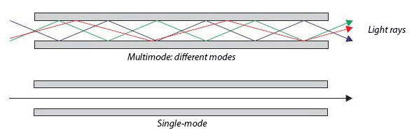
- Multi-mode fibers : Allow the use of multiple wavelengths, meaning that we can have multiple communications using a single medium (or bidirectional communications). They are typically used for short distances. The kernel of a Multi-mode fibers is quite large (from 50 to 65µm) which allows light to bounce on the edges, shifting the light and avoiding interferences with other light beams.
- Single-mode fibers : Allow the transmission of a light signal on a long distance. They have a much smaller kernel, that will avoid light from bouncing on the edges, and having a straight light beam, with less loss on long distances. The inconvenient is that they are more expensive and you must have 2 of them if you want a full-duplex communication.
When it comes to connectors, we also have 2 big families, which are squared connectors and round connectors. The main difference between the two is the density of connections.
Squared connectors (SC) are preferred to round for most desktop, PC and multimedia applications. They are also declined in 2 distinct types, UPC (Ultra-Polish Connectors) that stands for the ceramic end of the connector being perpendiculary polished (90° angle between the end of the connector and the kernel of the fiber) and APC (Angle-Polish Connectors) that ensures an 8° angle between the ceramic-end of the connector and the fiber kernel.
UPC connectors are less used than APC because parts of the light beam will be reflected away while inserting the other connector, causing a big loss doing so. APC connectors are especially designed to avoid that loss, and are more therefore more efficient.

The signal strength when using a fiber cable can be seen and measured using an Optical Time Domain Reflectometer.
As said at the beginning, the Physical layer is also in charge of the modulation and correction of the signal, but as we are only talking about the basics on this series, I will not be discussing those aspects, but maybe in another article if you want me to !
That's now it for the Physical layer of the OSI model, which can be very complex due to its close relation with physics, and is absolutely not abstract at all. But it's over, you've come through this tough part, and we're now moving on to layer 2, which is Data link, and we will have completed TCP/IP layer 1.
See you on the next article 😁

Top comments (1)
Choosing The Right Structured Cabling Infrastructure
Technology is moving at a fast pace. Cabling infrastructure must match your company needs. Choosing the best solution for your business in advance saves time and money. Infrastructure performs rather well for an average of ten (10) years and usually, modest cabling supports up to three (3) generations of active electronic devices.
tech-computer.fr/entreprise-cablag...