
As a part of my prep for AWS SAA-C02, I started learning the basics of how networking works in the cloud. This post has been written for sharing my learnings with my fellow community members from AWS User group Madurai.
Understanding Networking is essential to understand the way AWS Services communicate
internally as well as with the on premises infrastructure.
Let's begin with the most fundamental model of networking.
Table of contents:
OSI model (open systems interconnection)
This is a 7 layer model which conceptualises movement of information from one point to another either in LAN or situated in different parts of the world.
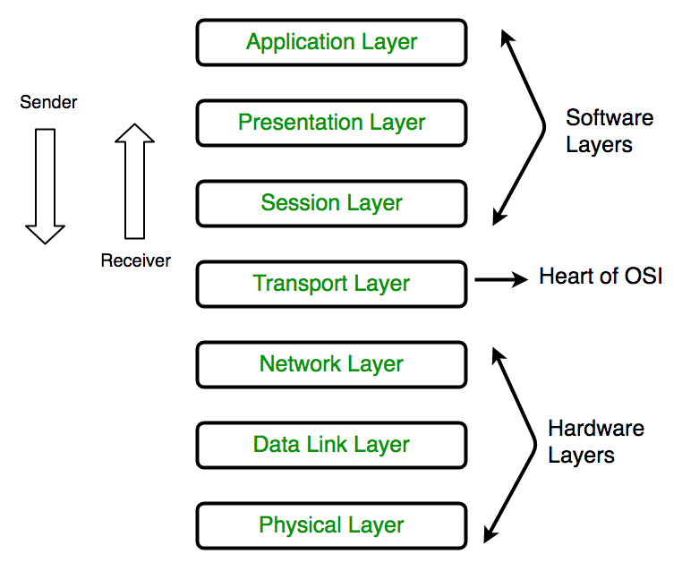
The above abstracted model depicts a network stack, the bottom 3 layers form the Media layer - show the movement of data one point to another.
The remaining layers form the Host layers - show how information is segmented,converted into an understandable format between each layer of the model.
The information sent by the sender(web browser) flows through these layers & reaches the receiver (network card) & is sent back over the same stack to the sender.
Let's understand the important layers that perform specific functions to interact with each layer above & below it.
Physical Layer :
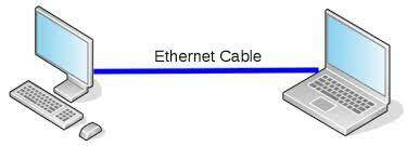
This layer specifies how raw bit streams should be transmitted & received between a device & a shared medium such as a Ethernet cable, fibre optic cable or Wifi.It defines characteristics such as pulse rates, modulation , the voltage levels,etc.
-The physical layer operates at the LAN level.
-Converts binary 1s & 0s to electrical, optical or radio signals
Why the need for Layer 2?
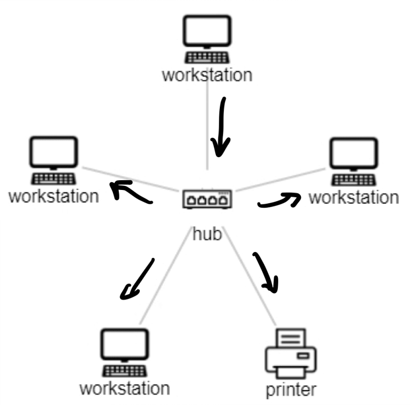
Let's take an example of a ethernet hub connecting multiple devices on a LAN
- It acts as a broadcast medium.
- Data transmission from one device is sent to all other devices
- Cannot uniquely identify devices. Thus one to one communication is not possible
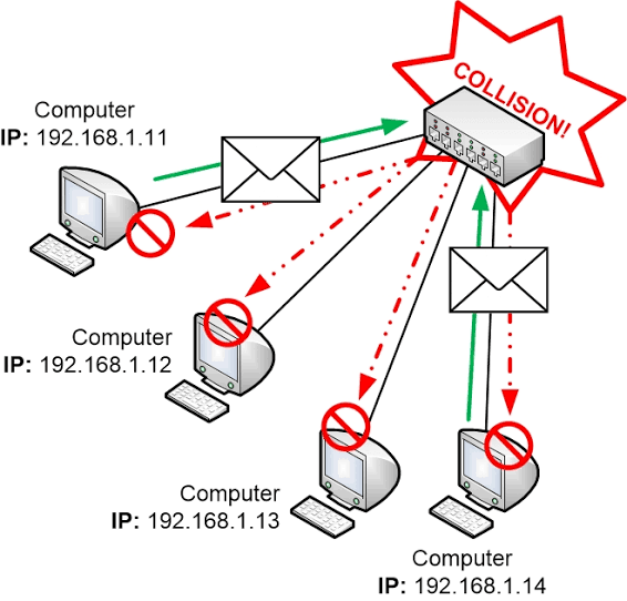
- No collision control. As all devices can broadcast simultaneously, collision happens & there can be loss or scrambling of data.
Data Link Layer :
This is an important Layer of the OSI model , it allows meaningful communication between the higher layers & Layer 1. It removes the drawback of the physical layer by allowing device to device communication.
For Data Link Layer to function a fully functional physical layer should exist.It means that Layer 2 is built upon Layer 1.
This Layer introduces MAC address to identify devices & frames for effective communication.
What is MAC address?
- Media access control (MAC) address are 48 bit hexadecimal addresses given to a network card.
- Its a combination of OUI (Organisationally Unique Identifier)that identifies the network card manufacturer & NIC (Network Interface controller).
What is a frame?
A frame is a container sent over a shared medium to the Layer 1. Layer 1 does not understand the Frame it simply transfers & receives them in the form of electrical/optical/RF signals over the shared medium.
Lets take an example of a Ethernet frame
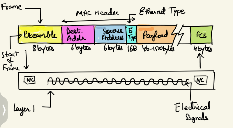
Here the ET denotes the Ethernet type which is the protocol used by Layer 3 to send the payload.
The destination & Source MAC uniquely identify the communicating devices. To broadcast the data to all devices the destination address can be mentioned as FF:FF:FF(all FF’s).
FCS denotes the Frame Check Sequence, its used for error detection & control.
Description of the above diagram:
Step 1: At the Source, Layer 3 sends the payload ,say in the form of a IP packet.
Step 2:This packet is encapsulated by Layer 2 into a frame as shown above & sent to layer 1 in the form of raw bits
Step 3: Layer 1 sends these bits over the shared medium to the destination Layer 1 & subsequently to Layer 2.
Step 4: Layer 2 retrieves the frame from the bits checks if the destination address is its own, extracts the IP packet & gives it to the layer 3 on the destination end , the protocol to be used in this Layer 3 is determined by the ET type.
In the OSI model,the lower layers are abstracted, it means that the devices at Layer 2 are unaware of the Layer 1. This is similar to when a user enters url in the browser & hits enter he/she is unaware of what layers the request passes through to get a corresponding response.
How does Layer 2 overcome Collision detection?
- Layer 2 uses CSMA/CD (Carrier Sense Multiple Access & Collision detection) network protocol to transmit data to Layer 1.
Lets understand how this works with the example of a Switch which is the network device that functions at the Data link layer
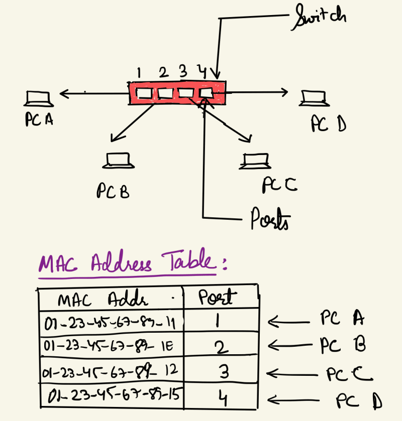
In Layer 2, switches are intelligent devices which maintain a MAC address table as shown in the diagram above. This allows a unicast (1:1)communication.
Initially this table is empty, as say PC A starts transmitting a frame the switch makes an entry in the table for the port PC A is connected to.
In the above diagram suppose that PC A transmits a frame with destination MAC address of PC C.
Step 1.: The switch receives the frame, stores & analyses it to find the destination system & its port based on the MAC address.
Step 2: It checks if there is a carrier on the communication channel ie if there is a transmission from PC C at the same time.
Step 3: If no, frame is sent to PC C. This is how the switch implements the CSMA protocol.
Step 4: If two devices for some reason transmit frame at the same time, switch ensures that the collision only limits to the port it occurs on rather than broadcasting it to other devices as in layer 1.
Step 5: In case a collision occurs, the switch implements a back off time wherein no communication occurs on the affected port. After the back off period,a retry is done to send the frame.
This is how, Switches operating at Layer 2 help to overcome the drawbacks of Layer 1.
Layer 2 works well at the LAN,WAN level & the internet is a combination of multiple interconnected Layer 2 networks but what if we want to connect multiple devices around the world.
Then we need the layer 3 (Network Layer) which we will talk about in the part 2 of this series.


Top comments (0)