(part one is here)
How to Build a Robust IoT Prototype In Less Than a Day - Part 2
Welcome back to our second article about creating a robust, bidirectional IoT prototype in less than a day using Arduino, Heroku, and Node-RED. If you missed the first part, we covered setting up Node-RED, adding security, and deploying to Heroku. In this article we'll look at creating our embedded system on the Arduino boards, connecting them to our Node-RED instance, customizing Sketches, and creating a flow that allows our devices to talk to each other. Let's get started.
What is Arduino IoT Cloud?
To connect the physical devices (boards) to the internet we will use Arduino IoT Cloud, a device manager and data visualization tool. After setting up an account at https://create.arduino.cc, we can create our first digital twin.
A digital twin is a logical online representation of a system. In Arduino, this is referred to as “Things” or “Apps”. We need to create two different Apps—one for the sensors, and another for the actuators. Then, we can associate a physical device (one of our MKR1010 boards) to it.
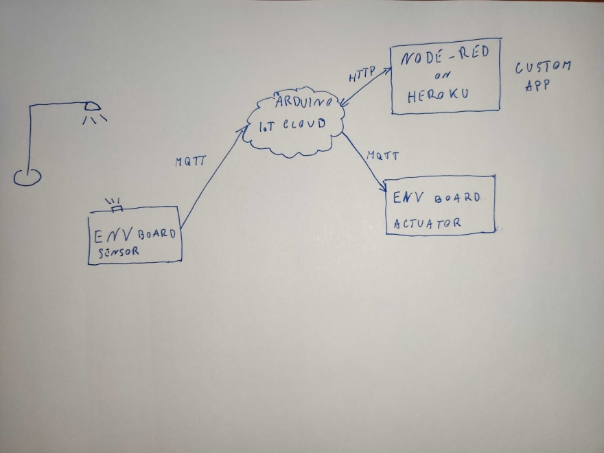
Here is the scenario: We want one of the devices to read the environmental luminosity (the sensor device), and the LED Matrix on the other MKR1010 (the actuator device) to display ON if the value of the luminosity is over a certain limit, OFF otherwise.
First, we need to create a new Thing and give it a name. I will call mine EnvSensors. Then, we need to associate a device. To do this, click “Configure a new device”.
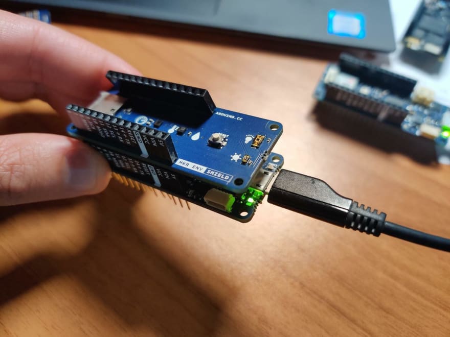
Before configuring the device, be sure to unplug any shield on the MRK1010 and plug it to your PC with a USB-micro cable. After installing the device, you can assign it a name. I will call it SensorsBoard.

In the first phase, the system will recognize the board; it should find an MKR1010. Then, it will upload a sketch to the board to automatically put an SSL certificate in the secure element for future encrypted communications. This process takes a few minutes, so be patient.


Once finished, we can continue creating our Thing. We need to create at least one property, luminosity, to start gathering data from our device.
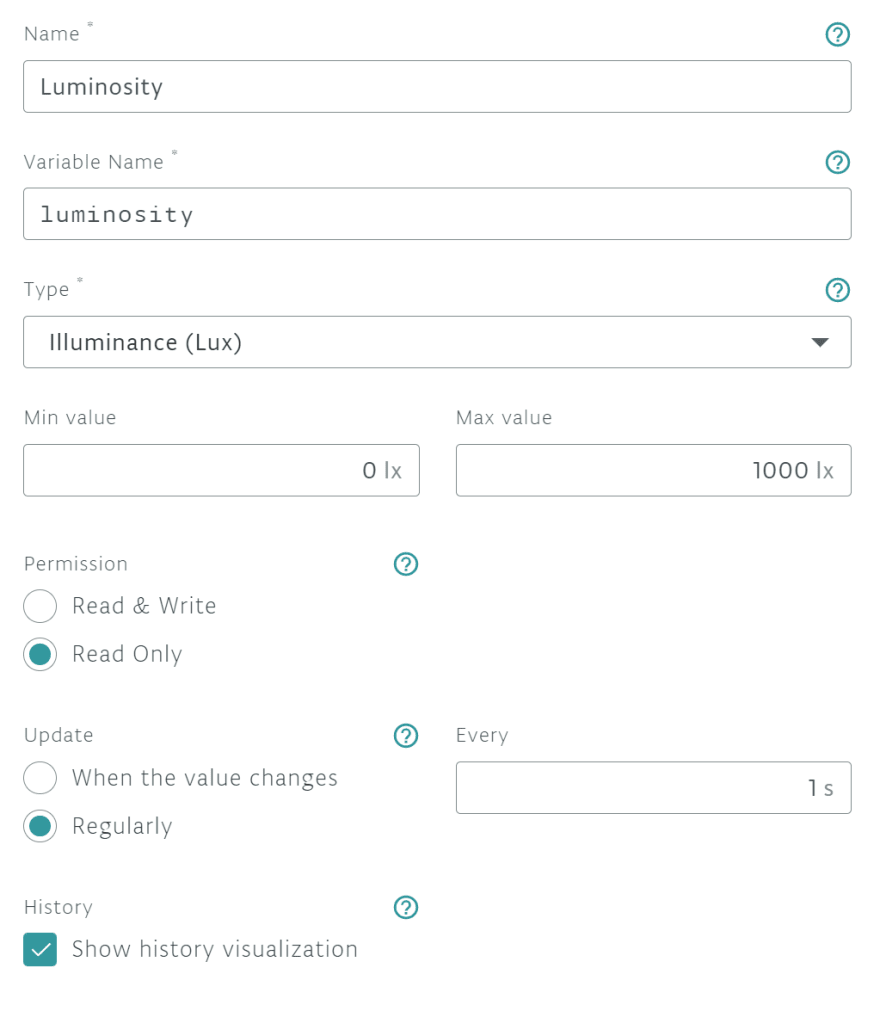
The property variable name will be Luminosity. The Type will be Illuminance. We will also set a min value of 0 for the obscurity, and a max of 1000 for high brightness. Then we set the permissions as “Read Only” because we can only read from sensors; we cannot write values to them. Next, we want to send luminosity values periodically, so we set the frequency to one-second intervals.
Finally, click “Add Property” and check to make sure the SensorsBoard is set as the associated device.
Now we can click “Edit Sketch”, which will open a web IDE. Arduino IoT Cloud automatically creates a template to send the data as we specified before—we just need to read the data from the sensor.
To read the sensors from the board, we have to put the MKR ENV shield on top of the MKR WIFI 1010. Then, we can plug the USB cable again in the board and modify the sketch a bit before the final upload.
On the software side, we need to add a library to read the values from the sensor. The following line is enough:
#include <Arduino_MKRENV.h>
Then, to avoid trying to read data before the initialization, we continue looping until the library loads and communicates with the sensors:
 if (!ENV.begin()){
    Serial.println("Failed to initialize MKR ENV shield!");
    while(1);
}
And here is where the magic happens! The automatically-generated file named thingProperties.h has already declared the luminosity variable for us:
float luminosity;
void initProperties(){
  ArduinoCloud.setThingId(THING_ID);
  ArduinoCloud.addProperty(luminosity, READ, 1 * SECONDS, NULL);
}
Remember, never change thingProperties.h, it is automatically generated and can fall out of sync if you change it manually.
The interesting part is we can use the variable luminosity as a normal variable. It will be sent automatically to the Arduino Cloud every second, as we specified in the interface.
To read the data we just need a few lines in our loop() function:
void loop() {
  ArduinoCloud.update();
  luminosity = ENV.readIlluminance();
  delay(50); //avoid reading the sensor too many times
}
We are almost done, but how do we connect the board to the WiFi network? We specify the network credentials in the secret tab:

Upload this sketch to your board.
Now it's time to verify that everything works as expected. So let's create a new simple dashboard in Arduino IoT Cloud:
https://create.arduino.cc/iot/dashboards
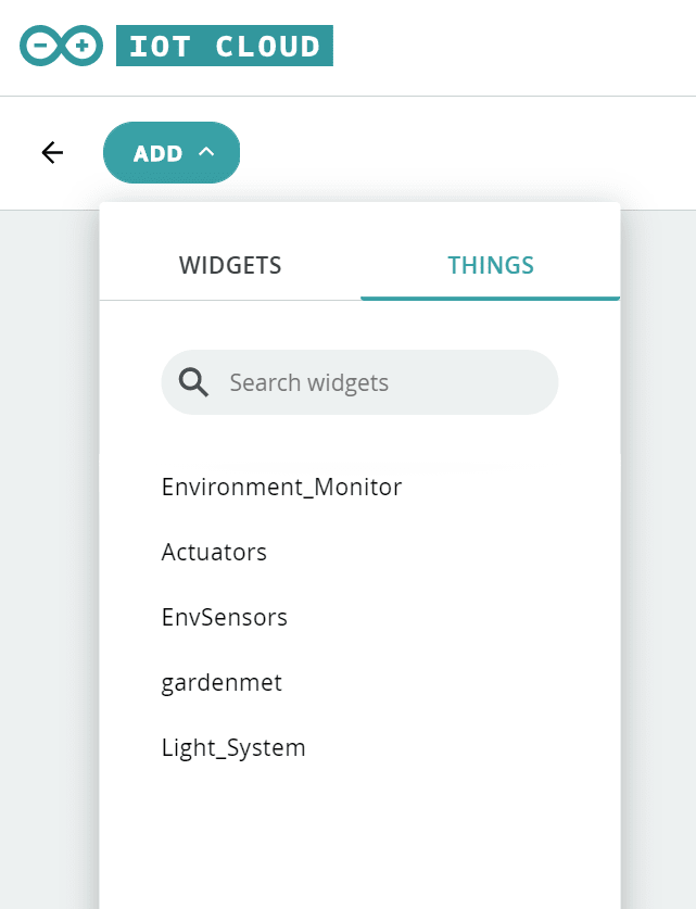
I named mine Sensors and Actuators. Now we'll add a new widget. In the Things tab, there's an easy way to create a dashboard with just one click. I selected my thing EnvSensors.
After placing the widget you should see the dashboard showing real-time luminosity data from the sensor:

Great! Now let’s create a new Thing and configure a new device. Let's call this new Thing EnvActuators and name the new device ActuatorsBoard. I suggest removing the SensorsBoard from your USB device. Avoid plugging in the LED matrix until after you configure the device.
The new Thing will have two variables: “display_text” to show online the same value the LED matrix is actually displaying, and a “switch” variable to tell us if the luminosity has reached a certain level. So we need to change the text on the display.
Display Test variable can be set as:
Name: Display Text
Variable: display_text
Type: Character String
Permission: Read and Write
Update: When the value changes
History: OFF
--
Name: LED Switch
Variable: led_switch
Type: ON/OFF (Bool)
Permission: Read and Write
Update: When the value changes
History: ON

After we click “Edit Sketch”, we have a new template to start with. There are two functions at the end of the sketch allowing the device to react when a property changes. Those functions are named CallBacks, and are called every time a property changes.
The following code allows you to change the value displayed in the LED Matrix every time the switch changes value from “true” to “false” and back.
void onLedSwitchChange() {
  if(led_switch){
    display_text = "on";
  }else{
    display_text = "off";
  }
}
While the main loop code is:
void loop() {
  ArduinoCloud.update();
  // Your code here
  MATRIX.beginDraw();
  MATRIX.clear();
  MATRIX.stroke(80, 80, 100);
  MATRIX.text(display_text, 0, 1);
  MATRIX.endDraw();
}
So every time the display_text variable changes, the LED Matrix clears and a new string is written on it.
You can find the entire code in my EnvActuators sketch.
Now we can upload the sketch to our MRK 1010 with the RGB Shield and add the Thing to the dashboard.
You should have a dashboard that looks similar to the image below:

Every time you change the led_switch toggle, the display text will change on both the display_text widget and on your physical device.

Interact with the Arduino Create IoT APIs
In order to create an application allowing the two different devices to speak to each other while adding our custom logic, we need to use the Arduino Create IoT REST APIs.
There are two kinds of APIs for Arduino IoT Cloud:
- A fully-documented REST Arduino IoT Cloud API
- A realtime API (only available for JavaScript as of the time of this writing), available on GitHub.
The system is throttled so you can't make more than 10 req/s for the REST API, but that's good enough for our use case.
In our first article, we learned how to deploy Node-RED on Heroku. This time we need to connect it to Arduino IoT Cloud by using an API token.
To obtain an IoT API token, go to the Things page and create one at the end of the page:
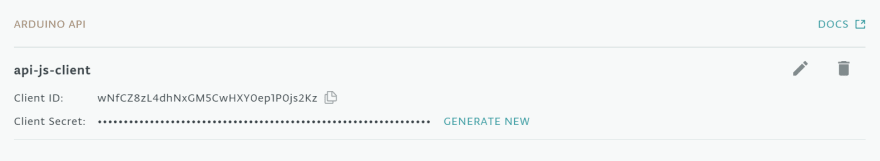
Be sure to keep your credentials in a safe place. (You won't be able to recover your client secret; you'll only be able to generate a new one.)
Connecting to Node-RED
If you followed the first article of this series, you should be able to access Node-RED from your Heroku Apps page. After accessing the app, you'll be able to see the Arduino blocks on the left panel and place them.
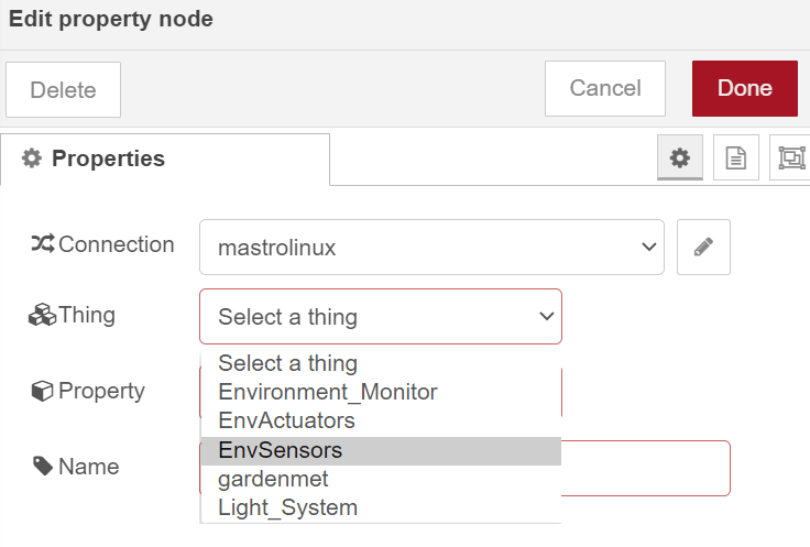
Double-clicking on a property will open a connection panel as shown below:

And clicking on the pencil will allow you to add the Arduino IoT Cloud API credentials.

Then, click “Add”. Now we can connect our luminosity property.
After clicking “Deploy” at the top right of the interface, we can begin to see the data flowing. Important: Nothing happens if you do not deploy your flow!
We are finally getting the property in Node-RED. The Luminosity I read is about 650 Lumen:

Design a Flow and Deploy It
Our flow is running on a Heroku Dyno. A Heroku Dyno is an application container with an ephemeral filesystem. This means your application will lose any data stored on a disk. Unfortunately, by default, Node-RED stores the flows and credentials on the filesystem.
There are many different strategies to avoid this, but they all require the development of a Node-RED configuration handler plugin. I created a simpler but effective solution. If we store the flows and the credentials in our source code, then they can be deployed on a new Dyno every time without losing our configuration. So I added the parameter flowFile: 'data/flows.json' in the settings.js file. Please see the previous article for more details.
Let’s run the application locally (in our node-red-private repo with the iot-proto branch).
$ heroku local
Now log into Node-RED to start creating the first flow. We should add an input property, a switch, and an output property. The input is connected to the luminosity sensor, while the output is connected to the LED Switch. In the middle, we'll place a switch block to control our LED value.
Our flow should look like this:
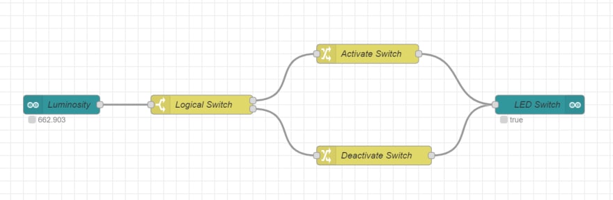
There are five components. The green ones are the Arduino properties, and include:
- An input Arduino Property block (connected to the luminosity)
- A logical switch, with the output 1 if the luminosity is above 300 and the output 2 if the luminosity is lower

- A set block to activate the switch

- A similar block to deactivate it
- An output Arduino Property block bounded to the LED Switch property
Don't forget to click “Deploy” once you are done.If you're feeling lazy, you can import my simple Arduino IoT Cloud Node-RED Flow.
Now we have to commit our code for the flows.
$ git add data
$ git commit -a -m ‘Saving the flow'
$ git push heroku iot-proto:master
And finally, we have the app in production!

We now have the RGB Matrix displaying ON if the luminosity is more than 300, and OFF if it less than 300.
We now have a fully-functional, bi-directional IoT prototype up and running in just a few hours, and ready for any projects you can dream up
Conclusion
Here is a quick recap of what we learned:
- How to set up boards in Arduino IoT Cloud
- How to set up properties for the Thing
- How the Sketch is automatically built from the system, and how to customize it. Sketches are available at:
- How to create a dashboard
- How to use the Arduino IoT Cloud API
- How to deploy Node-RED to Heroku
- How to make the Heroku website persistent (with encrypted credentials)
All of those steps allowed us to:
- Create a custom logic application on Node-RED
- Have two different devices talk to each other
By leveraging Node-RED, you can also add many integrations with third-party services.
Potential Improvements
In the future, I'd like to add proper persistence by using a Redis or Postgres storage supported by the Heroku Database & Data Management System. This will require writing a small js plugin to allow Node-RED to store the flows and configurations in a database. I found an old repo by Atsushi Kojo containing a PoC. The code is old but I will probably update it in the future. The repo is named node-red-heroku.
After I finish that setup, it will be possible to use a nice Heroku feature, the Deploy to Heroku button. This will allow a one-click setup of everything we've seen so far.
What’s Next?
In the next article, we'll create a working prototype of an entire custom Node.js application by using the Arduino Real Time Js Client working inside Heroku and interacting with Arduino IoT Cloud.

Latest comments (0)