Displays play a crucial role to communicate information, in any institute, organization or public. The information may be related to current situations, updates, or can be advertisements about the products. People are currently adapting to the idea of the world having information at their fingertips.A Dot-Matrix Display is made up of LEDs arranged or wired in the form of a matrix. Symbol, Graphics, Characters, Alphabets, and Numbers can be displayed with a Dot Matrix Display.
Understanding Dot Matrix Displays
A Dot-Matrix Display is made up of light-emitting diodes arranged or wired in the form of a matrix. Symbols, Graphics, Characters, Alphabets, and Numbers are displayed in applications by using Dot-Matrix Display and can be displayed together in constant as well as scrolling motion. Variable dimensions in which Dot Matrix Display is manufactured are such as 5x7, 8x8, 16x8, 128x16, 128x32 and 128x64 where the first number shows LEDs in rows and the second number shows LEDs in columns, respectively. Displays are available and can be manufactured in different colours such as Red, Green, Yellow, Blue, Orange, and White and multicolour.
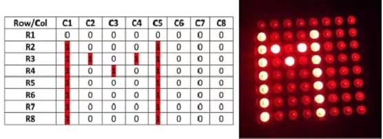
In DMD, If we powered different LEDs separately we need different I/O pins physically which is not reliable In an 8×8 matrix, the LED's would need 64 I/O pins, one for each LED pixel. In order to minimize the number of pins required to drive them, many LEDs are wired together in rows and columns. Therefore, by wiring all the anodes together in rows (R1 through R8), and cathodes in columns (C1 through C8), the required number of I/O pins is reduced to. 16. Each LED is addressed by its row and column number. You may manufacture it can be as common cathode or common anode. The matrix pattern is made either in row anode-column cathode or row cathode-column anode pattern. In row anode-column cathode pattern, the entire row is anode while all columns serve as cathode which is shown below, and it is vice versa in row cathode-column anode pattern. If we want to display any character or number then according to that number we have to pull down or high the pins of the matrix. For example, we have to enable row and the column pins as per the table given below to display a character M where the on LED is denoted by red dot.
Displaying the Letter “M” on a Dot Matrix Display

Chart for displaying character M on Dot matrix Display
Creating the System Design and Circuit Diagram
The following fig shows the interfacing diagram of Dot Matrix Display With Arduino.

Circuit diagram of dot matrix display interfaced with Arduino
Above fig shows hardware interconnection between Arduino nano (ATMEGA328P), HUB (pins) of Dot matrix display(DMD 16*96)
Pin Configuration of the Dot Matrix Display (DMD)
- Pin no. 1 : It is a (N0E) enable pin used to enable our main element of the project which is a dot matrix display
- Pin no. 2 : Digital communication pin A is connected to pin no 9 which is the D6 pin that is the digital out pin of Arduino
- Pin no. 3, 5, 7, 9, 11, 13, 15 : are connected to pin no. 4 which is the ground pin of Arduino
- Pin no. 4 : digital communication pin B is connected to pin no 10 which is a D7 pin which is also a digital out pin
- Pin no. 6 : Data line C for communication
- Pin no. 8 : this is the CLK pin connected to pin no 16 which is the D13 pin of Arduino
- Pin no. 10 : this is a system clock pin connected to pin 11 of Arduino, which is the D8 pin
- Pin no. 12 : which is system ready check is connected to pin no 14 of the Arduino which is a D14 pin
Scrolling Text on a Dot Matrix Display (DMD)
The coding part
#include <SPI.h>
#include <DMD.h>
#include <TimerOne.h>
#include "SystemFont5x7.h"
#include "Arial_Black_16_ISO_8859_1.h"

#define DISPLAYS_ACROSS 3
#define DISPLAYS_DOWN 1

DMD dmd(DISPLAYS_ACROSS, DISPLAYS_DOWN);

void ScanDMD() {
  dmd.scanDisplayBySPI();
}

void setup() {
  Timer1.initialize( 3000 );
  Timer1.attachInterrupt( ScanDMD );
  dmd.clearScreen( true );
  Serial.begin(115200);
}

void loop() {
  dmd.clearScreen( true );
  dmd.selectFont(Arial_Black_16_ISO_8859_1);
  const char *MSG = "WELCOME TO VED ELECTRONICS";
  dmd.drawMarquee(MSG, strlen(MSG), (30 * DISPLAYS_ACROSS) - 1, 0);
  long start = millis();
  long timer = start;

  while(1) {
    if ((timer + 39.9) < millis()) {
      dmd.stepMarquee(-1, 0);
      timer = millis();
    }
  }
}
Conclusion
The prototype of the Arduino-based display toolkit was effectively designed. This prototype has to be facilities to be integrated with the display board it can solve the problem of instant information transfer on the campus, and it is the best replacement for regular flex boards. In the future, we can add an IR sensor to detect human motion where the display is mounted and the output of that sensor given to the primary of the relay. If the IR sensor detects a human around display then its output is given to display and the NO of the relay get closed, and the display will display our message for some programmed time. If there is no action around the display, then it will undergo standby mode and reduced power consumption.
.ct-268635{color:#F92672;}
.ct-183901{color:#F8F8F2;}
.ct-141567{color:#E6DB74;}
.ct-253592{color:#A6E22E;}
.ct-674544{color:#AE81FF;}
.ct-049000{color:#66D9EF;font-style:italic;}
Arduino UNO Explained: Features, Shields, IDE: Nano, ESP32, Interfacing a 16x2 LCD display with 8051 microcontrollers
Keywords:
embedded, dmd, arduino, display, microcontroller, electronics


Top comments (0)