If you have UART debug port on your device, you can retrieve various information from there. If you are dealing with IoT, you can access to the shell via UART on some device. Also, if you are dealing with PC, you can retrieve output from the UEFI/BIOS early in the boot phase. Retrieving outputs from serial connection is often better because, such interface like HDMI aren't accessible until late in the boot phase.
In this post, I'll explain how to get the serial output from UART on UP squared pro Atom board.
Environment
I will be using followings in this article (hereinafter, these are called by the terms in parentheses).
- Windows 10 PC that has USB 3.0 port (Host PC)
- UP Squared Pro Atom Quad Core 04/64 (UP2 board)
- USB to 3.3v TTL Header (USB to TTL cable)
- USB 2.0 pin header cable EP-CBUSB10PFL01 (pin header cable)
- Male-to-Male Jumper Wire 3x (jumper wire)
Followings are needed for flashing the BIOS to the one that's build with DEBUG mode.
Install FTDI Driver
In order to use USB to TTL cable, you have to install FTDI Driver in your Host PC if you don't have one. You can download from here by clicking "Windows FTDI Driver" under "Software & Drivers". This is because the above cable uses FTDI chip for handling USB. FTDI chip is one of the most popular USB to TTL converter IC, and this helps converting USB signal to UART signal (FTDI is a company name).
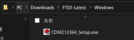
You will see the following installer so execute it to install the FTDI Driver.
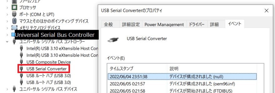
To check if you have installed it correctly, connect USB to TTL cable to your Host PC and open device manager. If you have "USB Serial Converter", then the installation is success.
Flashing BIOS to the DEBUG built image
BIOS image built with DEBUG mode often outputs debug info to the serial output. This step is not necessary if you have some module that outputs message to the serial output, but if you don't have any, you can use this to check if the setup is successful.
The BIOS image I will be using is Intel Atom® Processor E3900 Series (Apollo Lake) Up Squared Board Flash Images R .71. You will see two images included in the file, one with "R" and one with "D" in the name. Use the image with "D" in and flash that image to UP2 board. How to flash BIOS is explained in my previous post.
Setting up the UART connection

Connect just like the above image. The pins which is important when using UART is GND, TXD, and RXD. Looking at up-community wiki, it says black cable is GND, white cable is TXD, and red cable is RXD. You have to connect to the coresponding pin shown below.

(image from Gearmo Site)
Other important information to use UART besides pin is baudrate. This is the speed of serial connection. It says on the wiki that the baudrate is 115200bps for this board.
After connecting, you need to configure serial client. Download PuTTY on your Windows host if you don't have one. Open PuTTY and select "Session" from the Category. Then, configure it like below.
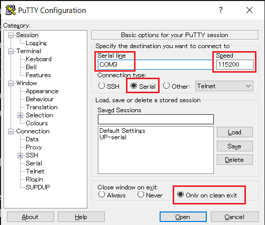
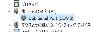
For serial line, you can check the device manager to see what COM port it is. In my case, it was "COM3".
Next, select "Serial" under "Connection" in the Category and configure it like below.

These configurations are written in the wiki.
Testing
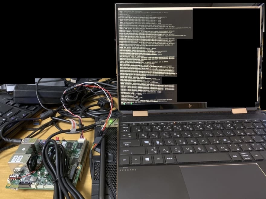
Now let's give it a shot. Make sure you plugged the USB to TTL cable to your Host PC and had the PuTTY configured. Click "Open" button in the PuTTY window, and if all the configuration are successful, black screen will show up without any errors. After that, power on UP2 board and see if it outputs tons of debug information.

Top comments (0)