
As a frontend developer primarily writing Javascript I'm used to building on the shoulders of giants.
There are so many layers between my code and the hardware it runs on now that it seems a bit like magic.
It's nice to spend some of my free time getting a bit closer to the metal.
The Initial Repair
This story starts over the summer when my Zodiac Z200 pool heater failed. The LCD panel died but the buttons still worked. No biggie I don't need the display. Two weeks of nice warm swimming later it kicked the can completely. 😢

I'd recently spent months building a breadboard computer based on the
Ben Eater video series ( which I highly recommend ) and spent many nights watching the 8 Bit Guy on YouTube fixing up old 80's computers. I love watching them restore old hardware and it gave me the confidence to maybe try a DIY repair myself! The unit was out of warranty, what did I have to lose?
I pulled the top off and had a look inside. My first thought was that although the whole unit was dead, the LCD panel failed first so I'll start there.
Taking a look at the circuit board you can see it's in pretty poor shape, everything is kind of coated in an oily sludge and you can see a bunch of exposed copper.

Using a multimeter I verified that most of those dodgy looking tracks were in fact working. A short track up the side had no conductivity so I soldered on a jumper wire to bypass it. Voilà we're back in action!

I was pretty stoked that I was able to apply lessons learnt from watching The 8 Bit Guy repair a Commodore 64 BUT looking at the state of that board I needed a more permanent solution.
Could I Build My Own Display Board?
This got my thinking, would it be possible to replace the display board completely. Could I replace it with something connected to the network and automate it?
Could I get to the point where I could say "Ok Google, What's the pool temp?" and get a response?
So I set out trying to determine how this board worked. The display board connecter was labeled G,V,A,B which meant nothing to me. I pulled out the magnifying glass, polished off some oily sludge and tried to read the labels on a few of the ICs.
One of them was 7517(something)a. Googling a bunch of options for the missing digit I came across the SN7516A. A Differential Bus Transceiver.
What exactly is a Differential Bus Transceiver? I have no idea but according to the data sheet it's used for "Low Speed RS485 communication (5 Mbps or less)"
Jackpot! I'm not sure what RS485 is but I know what RS232 is, it's serial protocol and maybe this is similar.
From the authoritative source Wikipedia
"RS-485 is a standard defining the electrical characteristics of drivers and receivers for use in serial communications systems... RS-485 signals are used in a wide range of computer and automation systems."
It turns out RS485 is a serial protocol just like RS232 but over a shared bus, if that's what it's using I could piggy back my own device on the bus and easily snoop on the traffic. I might even be able to control the heater while leaving the screen connected.
The hardware
I had some experience with the ESP32. It's an amazing little chip, compatible with the Arduino IDE including a built in WIFI radio. I have a bunch of these floating around from a Christmas light project which would work nicely.
Next I needed a module to talk RS485. The GPIO pins on the ESP32 can switch between 0V and 5V which isn't suitable for RS485. I needed one of those pesky bus transceivers!
I ordered one of these and look at that! The pins are labeled VCC, A, B, GND, we're in business.

Building the module
The ESP32 has a few built in hardware serial ports. The second serial port is exposed on pins 16(RX2) and 17(TX2). The wiring was very simple, I connected one side of the MAX485 chip up to the bus and the other side to the ESP32.
 Pool
Heater.          MAX485        Display
 |A|------------->|A |---------->|A|
 |B|------------->|B |---------->|B|
 |G|------------->|G |---------->|B|
 |V|------------->|V |---------->|B|
                  |. |
                  |. |             ESP32
                  |DI|---------->|17 TX2 |
                  |DO|---------->|16 RX2 |
                  |DE|---------->|5  GPIO|
                  |RE|---------->|18 GPIO|
It ended up looking like this:
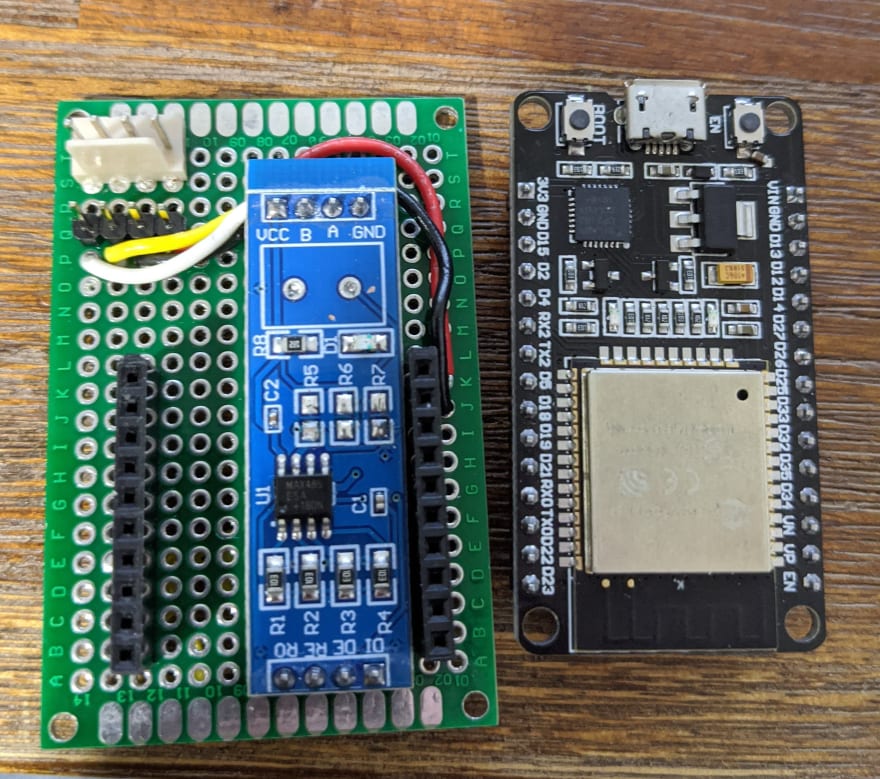
The pin headers I used for the ESP32 made it sit quite high. Combined with the very different layout of the ESP32 and MAX485 I was able to stack them on top of each other for a very compact little module.

Before doing anything else I wanted to verify that I could piggyback this module on the bus without breaking anything.
First I verified that the VCC / GND pins coming from the heater were in fact 5V. I needed 5V to power the ESP32 and without that I would be in a bit of trouble.

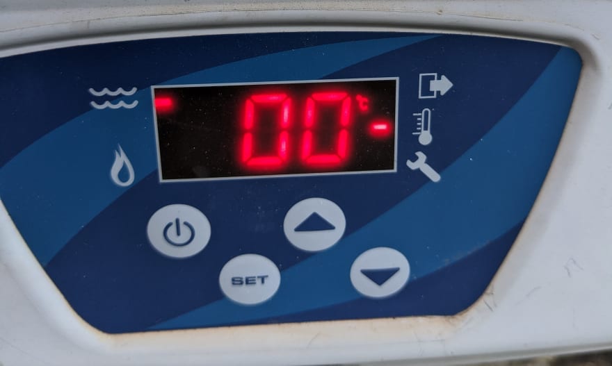
I hard wired DE and RE to ground which should disable the module and plugged it in. Unfortunately I was greeted with a 00 and the buttons did not work. 😢
Uh oh, I'd read online that I would need to remove the termination resistor from my RS485 module before it could share a bus so I removed R7 but it didn't help.
At this point I was a bit stuck and out of my depth, maybe if I had an oscilloscope I could try to diagnose what was going on. I didn't have one and don't really know how to use one anyway 😂
After sleeping on it for a few days and doing a bunch of googling I stumbled across a forum post from a user having the same issue with these exact modules. Each module includes a 10k resistor pulling the A data line to VCC and a 10k resistor pulling the B data line to GND. The idea is that the data lines will be pulled to a known voltage when nothing is on the bus.
Most of the information I'd read said it should be harmless to leave these resistors on every device connected to the bus but this forum user said otherwise, they should only be on the devices at either end of the bus!
I removed two more resistors from my module, plugged it in and the heater came alive. We're back on track!

First bytes
Now that I had the hardware installed I was keen to pull some data and see if I could make some sense of it.
The MAX485 chip has two enable pins, DE for transmitting and RE for receiving. The DE pin is active high and the RE pin is active low. It seems a bit weird that they're different but it's very convenient. It means you can tie the two pins together and set them both HIGH when you want to send or leave them LOW to receive.
I wrote a very small Arduino program that set the enable pins to read, configured the serial port and then streamed any bytes received to a connected TCP client.
I took a guess on the serial port settings, 9600 Baud, 8 bits, no parity 1 stop bit. I didn't expect it to work first go but even if the settings were wrong I should see some data.
With all the networking removed it looked something like this:
#define PIN_RX2 16
#define PIN_TX2 17
#define PIN_DE 5
#define PIN_RE 18

void setup() {
  // Setup WIFI (Removed)

  pinMode(PIN_DE, OUTPUT);
  pinMode(PIN_RE, OUTPUT);
  digitalWrite(PIN_DE, LOW);
  digitalWrite(PIN_RE, LOW);
  Serial2.begin(9600, SERIAL_8N1, PIN_RX2, PIN_TX2);
}

void loop() {
  // Accept TCP connections ( Removed )

  char data = Serial2.read();
  client.write(data);
}
Connecting to the device I was greeted with this 😇
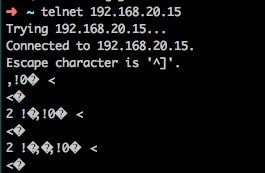
A nice steady stream. I was seeing a block of data about twice a second including a nice bell escape character🔔 🔔 🔔. Music to my ears. I think I even guessed the correct serial port settings!
Decoding the protocol
I wanted to read the following information:
- Is water flowing
- Is the power on
- What is the set point temperature
- What is the water temperature
I knew it all had to be there because it was available on the current display.
I started out by dumping the data into files on my laptop using netcat which I could pipe into hexdump. Here is a snippet of some of the data I captured.
0000000 01 10 00 2c 11 00 11 00 11 00 21 00 00 00 72 00
0000010 01 00 dc 00 20 00 20 00 00 1e 14 00 03 3c 0a 05
0000020 00 3c 00 1e 00 1e 03 00 d2 0a 32 07 03 20 00 00
0000030 80 8c 01 10 00 2c 11 00 11 00 11 00 21 00 00 00
0000040 72 00 01 00 dc 00 20 00 20 00 00 1e 14 00 03 3c
0000050 0a 05 00 3c 00 1e 00 1e 03 00 d2 0a 32 07 03 20
0000060 00 00 80 8c
One of the challenges I faced was that the captured data was missing any timing information. Observing the data in real time you could see obvious blocks in the data with a lot of repetition. I updated my Arduino code to print out whatever was in the serial buffer in one chunk followed by some whitespace so it was obvious where the packet boundaries were.
I was receiving a packet like this about twice a second, always the same length. I figured this must be the current status being sent to the display.
00000000: 01 10 00 2C 10 00 10 00 0F 00 21 00 00 04 30 00
00000010: 00 00 DC 00 20 00 20 00 00 1E 14 00 03 3C 0A 05
00000020: 00 3C 00 1E 00 1E 03 00 D2 0A 32 07 03 20 00 00
00000030: 5B A1
The current set point temperature was 32°C which is 0x20 in hex. That shows up a few times in the capture but by adjusting the temperature and watching what changed I was able to narrow it down.
After heading in and out of the house a dozen times turning the water on and off I was able to identify all the data I cared about. The most challenging were the water flow and heating status. They ended up being single bit flags in byte 13 and 14.
bool packet_read_power_on(struct Packet packet) {
    return packet.buffer[16] == 1;
}

uint8_t packet_read_set_point(struct Packet packet) {
    return packet.buffer[20];
}

uint8_t packet_read_water_temp(struct Packet packet) {
    return packet.buffer[4];
}

boolean packet_read_flow(struct Packet packet) {
    return (packet.buffer[13] & 0x04) == 0;
}

boolean packet_read_warm_up(struct Packet packet) {
    return (packet.buffer[14] & 0x40);
}

boolean packet_read_heating(struct Packet packet) {
    return (packet.buffer[14] & 0x02);
}
One thing that did stand out was that the last two byes changed dramatically all the time, leading me to suspect some sort of checksum. I found this online CRC calculator and pasted in one of my packets.
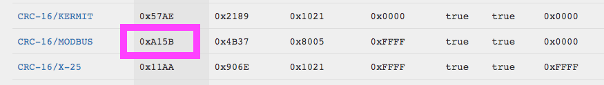
The two final bytes showed up as one of the options, so it was a checksum, and it had a name Modbus!
I have heard of Modbus but never really dealt with it. Reading the spec for Modbus over RS485 packets are delivered in blocks with defined gaps between them. It's a very flexible protocol the only things specified are:
- Byte 1 is the address
- Byte 2 is the function code
- The final two bytes are 16 bit CRC of the message.
The rest is really up to the implementation.
Following the same procedure to as decoding the status messages it was trivial to also capture the commands sent from the control panel when I pressed a button. I could even calculate the correct CRC!
Building a Home Assistant component
Fast forward a bit and I'd built a simple terminal CLI for the heater, I could telnet in and press keys to control the unit, it would also spit out a nice table with the current temperature and status.
What I really wanted was voice control!
I'm running Home Assistant on a Raspberry Pi which can control my Daikin Air Conditioner. One cool feature is that climate devices in Home Assistant can be exposed to Google Assistant so If I build a climate device integration for Home Assistant I would get Google integration for free!
For this I really needed a REST API for my ESP32. Fortunately the standard library actually includes a web server! It's very basic but that's all I need 😀
server.on("/status", HTTP_GET, get_status);

void get_status() {
    struct Status status = heatpump_get_status();
    String response = "{\n";
    response += ("  \"powerOn\": " + bool_string(status.powerOn) + ",\n");
    response += ("  \"heatingOn\": " + bool_string(status.heatingOn) + ",\n");
    response += ("  \"waterFlowing\": " + bool_string(status.waterFlowing) + ",\n");
    response += ("  \"setPointTemperature\": " + String(status.setPointTemperature) + ",\n");
    response += ("  \"waterTemperature\": " + String(status.waterTemperature) + "\n");
    response += ("}\n\n");
    server.send(200, "application/json", response);
}
While cleaning up the codebase and adding a REST API I realised how BAD I am at C. Back in 2006 I was a full time C++ developer and I thought I knew it pretty well but it's not like riding a bike!
You end up taking a lot of things for granted in higher level languages.
Take for instance this snippet
struct Packet {
    uint8_t* buffer;
    int length;
}

struct Packet getPacket() {
    uint8_t buffer = { 0x00, ..., ... };
    struct Packet packet;
    packet.buffer = &buffer;
    packet.length = sizeof(buffer);
}
Seems pretty innocuous, I'm not touching malloc() of free() what could go wrong? Turns out I'm saving a pointer to a local variable from the stack that's going to be freed! 🤮
The final step is to switch from bad C to bad Python. I won't bore you with the details but Home Assistant include some demo components in their source tree. It's pretty easy to take the demo Climate device and hack it up to talk to a REST API on the local network.

If you're interested in any of the code from this project you can find it here on GitHub
Ok Google
Now for the final test!
Conclusion
Thanks for reading to the end, it was a heap of fun stepping out of my comfort zone and tackling a hardware project with C and Python mixed in 😀


Top comments (5)
Great writeup!
Great job man, thanks for sharing.
Wow, amazing job.
So cool! (I mean warm)
Hi man
Got same Issue, 00 on display and buttons don’t work, any chance to repair It without building new module?
Thnx