
With IoT becoming such a large part of our lives, I have often come across developers who want to get started but have no idea how. Why is that? Well, it is probably related to one of my favorite programmer jokes:
How many developers does it take to screw in a light bulb? They can't, it's a hardware problem.
I am one of these people, I struggle to understand the hardware, but I really enjoy writing the software. That was until I started playing with XinaBox. These lego like electronics, allow you to clip different chips together and get prototyping quickly and efficiently. All XinaBox chips are based off of other popular chips used in prototyping, making it easy to find libraries and tutorials.
What you will need
- A computer with the Arduino IDE installed
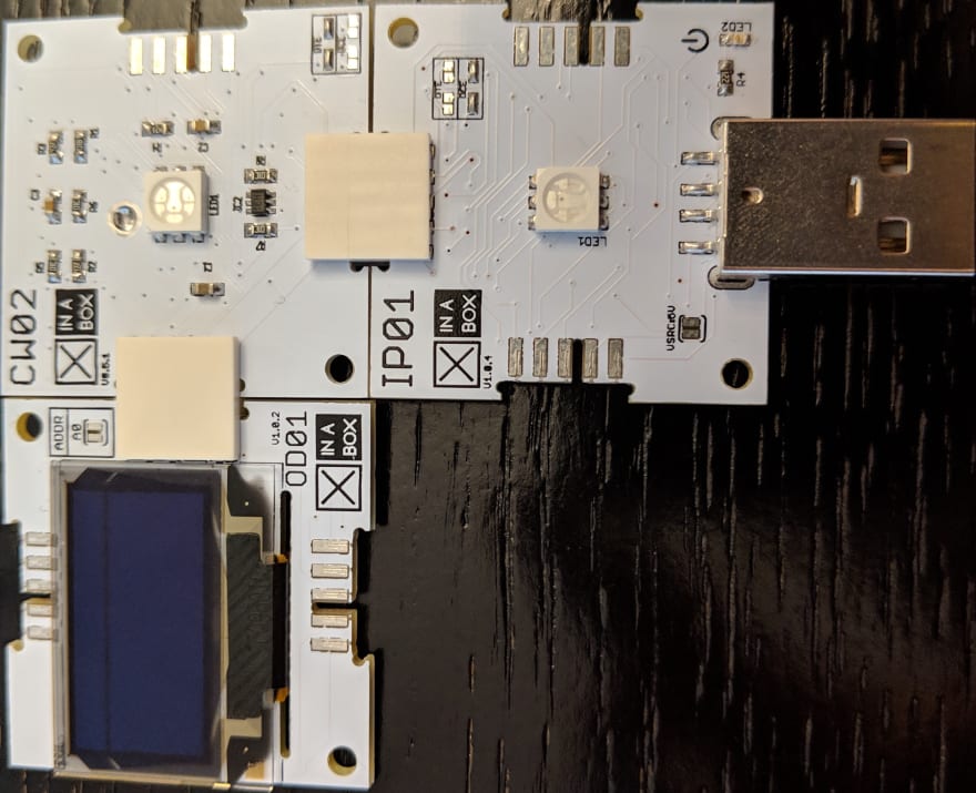
- The core processing chip: XinaBox CW02
- The programming interface: XinaBox IP01
- The LED screen: XinaBox OD01
- The temperature sensor: XinaBox SW02
- Three xBus connectors to put everything together
Blinking an LED
Let’s start with the electronics equivalent of “Hello World”, blinking an LED. The chip we will be using as our core processing chip for this tutorial is the XinaBox CW02 which has an Espressif ESP32 chip. In order to be able to program for that chip we need to make some configurations changes to the IDE:
- Open Preferences and in the additional boards field paste the following URL:
https://dl.espressif.com/dl/package_esp32_index.json - Then in Tools - Boards - Boards Manager search for ESP32 and install it.
Once installed, you will need to select ESP32 Dev Module as the board you are programming. If you struggle with this part, check out the official instructions.
In order to program our core chip we need to be able to plug it into our computer, for that we will use one of the programming interface xChips, the IP01. Clip the two chips together and plug them into your USB port:

Once plugged in you can select a port in the IDE under the tools menu (if Port is disabled try closing the IDE and opening it again). Port names differ based on device and operating system, for example, on my Mac the port is named /dev/cu.usbserial-...., while on my colleague's Windows machine the correct port was COM8.
Last bit of setup we need to do before we can blink the LED is to install the xCore library, this library provides us with some basics for controlling the xChips. You can download the zipped file from the XinaBox GitHub account and import it into your IDE by going to Sketch - Include Library - Add .ZIP Library...
Now we are finally ready to code, the CW02 chip comes with an RGB LED and this is what the code for blinking this LED looks like:
#include <xCore.h>
#include <xVersion.h>

#define RED_PIN 25
#define GREEN_PIN 26
#define BLUE_PIN 27

void setup() {
  Wire.begin();

  pinMode(RED_PIN, OUTPUT);
  pinMode(GREEN_PIN, OUTPUT);
  pinMode(BLUE_PIN, OUTPUT);
}

void loop() {
  digitalWrite(RED_PIN, HIGH);
  delay(1000);
  digitalWrite(RED_PIN, LOW);
  digitalWrite(GREEN_PIN, HIGH);
  delay(1000);
  digitalWrite(GREEN_PIN, LOW);
  digitalWrite(BLUE_PIN, HIGH);
  delay(1000);
  digitalWrite(BLUE_PIN, LOW);
}
This code does the following:
- It includes the xCore library
- It defines the red, green and blue pins
- It initialises the core chip by calling
Wire.begin();and sets the three pins to output mode - It then loops through turning each colour on and off every one second.
Hit the upload button in the Arduino IDE (the arrow in the top left corner) and you should have a blinking LED.
Actual Hello World
The next chip we are going to add onto our setup is the OD01. This little LED screen can do quite a lot, but for now let's just make it say hello. Again we need to start by downloading and importing the zipped library from GitHub. Then unplug the chips from your computer and clip in the screen chip.
Once that's in we need to make some changes to the code:
-
Include the OD01 library and define the property:
#include "xOD01.h" xOD01 OD01; -
In the setup method after we initialise the core chip we need to initialise the screen:
OD01.begin(); -
There are multiple methods that can be used with the screen, the most common of which are
print,printlnandclear. Add the following code to the bottom of the loop method:
OD01.set2X();
OD01.print("Hello ");
OD01.set1X();
OD01.println("World");
delay(5000);
OD01.clear();
Upload the new code and see the changes in action.
Hows the weather
When we first got these xChips some of them were brand new, which meant that there were no libraries available for them on the XinaBox GitHub pages. One such chip was the SW02. It is a temperature, humidity, pressure and gas resistance sensor all in one and with it being so hot in Johannesburg lately this is the one I really wanted to play with. As I mentioned earlier all xChips are based on other popular prototyping chips, and this one in particular is based on the Bosch Sensortech BME680. After some digging, I found out how to make this chip work without having the XinaBox specific library.
Open up Sketch -> Include Library -> Manage Libraries..., search for BME680 and install ClosedCube BME680 (if you read the description at the bottom you will see that it says it is for the Bosch Sensortech BME680 sensor). Unplug your chips and add the SW02.

Now for some more code changes:
-
Include the library and define the property:
#include "ClosedCube_BME680.h" ClosedCube_BME680 bme680; -
Initialise the sensor (don't forget to call this method from the
setup()method)
void initSensor() { bme680.init(0x76); bme680.reset(); bme680.setOversampling(BME680_OVERSAMPLING_X1, BME680_OVERSAMPLING_X2, BME680_OVERSAMPLING_X16); bme680.setIIRFilter(BME680_FILTER_3); OD01.println("Connected to sensor"); digitalWrite(GREEN_PIN, HIGH); } -
Get the readings by replacing the
loop()method with the following:
void loop() {
    bme680.setForcedMode();
    double temperature = bme680.readTemperature();
    OD01.print("Temperature: ");
    OD01.print(temperature);
    OD01.println(" C");
    double pressure = bme680.readPressure();
    OD01.print("Pressure: ");
    OD01.print(pressure);
    OD01.println(" hPa");
    double humidity = bme680.readHumidity();
    OD01.print("Humidity: ");
    OD01.print(humidity);
    OD01.println(" %");
    uint32_t gas = bme680.readGasResistance();
    OD01.print("Gas: ");
    OD01.print(gas);
    OD01.println(" Ohms");
    delay(10000);
}
Hit upload and see the readings displayed on the screen.
Conclusion
So we have some cool chips setup and working together. You can take a look at the final code on my GitHub. In part two, I would like to show you how to get this data to the cloud.


Top comments (1)
Note: On newer versions of MacOS you may need to install this USB to UART Bridge Driver for the port where the ESP32 Dev Board is plugged in to be detected.