
This is a writeup I've moved here from my personal website. It was originally published on 4/13/19
The asciiPad SG-6 is an aftermarket Sega Genesis controller with extra buttons and macro features. As a kid, I had no idea what any of the weird switches did. I just sort of flicked them up and down until the controller worked as I expected. As an adult, I started wondering how the controller is able to support more buttons than the stock controller, let alone the frame rate slowing capability I remembered as a child. It’s a mystery I couldn’t just leave alone. To the batcave!
I’m mostly just getting started as a hardware reverser, so my tools are nothing fancy. For this, I used a bunch of jumper wires, male and female DB-9 breakouts, and a super budget logic analyzer. All told, materials cost around $20. Here’s the setup.
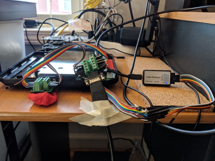
I wanted to capture the signals coming from the controller when different buttons were pressed and different modes were set. The controller is powered over the serial connection, though it uses a non-standard pinout. Ground is pin 8, VCC at 5v is on pin 5. The other pins float high at 4v9. I checked all of this with a multimeter (mine is nothing fancy) before hooking anything up. Measure twice, cut once, as the saying goes.
The controller should be completely standalone, so if you have a bench power supply, you can just set it to 5v and hook the + rail to pin 5 and the – rail to pin 8. I didn’t do this. Instead I opted to use a female DB-9 breakout connected to a male DB-9 breakout connected to the controller in order to power the controller and provide access to the pin signals. I did this because it’s cheap and it works. My little logic analyzer is connected to the male breakout with some jumper wires so it can read the pin logic levels. I collected traces for pins 1–4, 6, 7, and 9 (everything but the ground and VCC pin).
From there, it was time to have some fun. I started with powering on the Sega and taking a trace to see if there were any bootup signals sent over the line by the controller or the Sega. There aren’t — the lines all just go high. Then I started taking traces with individual buttons. Which quickly became… odd.

For all of the pins, a logic level of 0 (the pin being high at 4v9) indicates that the button associated with that pin is not being pressed. A logic level of 1 (the pin being being driven to ground) indicates that the button is being pressed. The standard controller pinout generally associates one button with each pin, however there are a couple of cases where the pins are multiplexed and two buttons are capable of driving the pin. In the latter case, a special Select pin differentiates the two buttons by being either high or low. For example, the Start button and the C button are multiplexed on pin 9 — if the Select pin is low, and pin 9 is low, then this is interpreted by the Sega as the Start button being pressed. If the Select pin is high and pin 9 is low, it is interpreted as the C button being pressed.
When I started pressing buttons on the asciiPad, only some of them affected the logic level on the pins. Really important, standard buttons, like A and Start, didn’t seem to have any effect on the pin outputs. But, you know, the asciiPad has a bunch of toggle switches and, who knows, some of them might be futzing up the operation of the buttons. It also has this nice “mode” button which, hell if I know what it does. It seemed like the next logical step was to hook the Sega up to a TV and get some intuition about what the odd buttons on the controller actually do, instead of relying on my decades old memories of how it worked from playing video games with my brother.
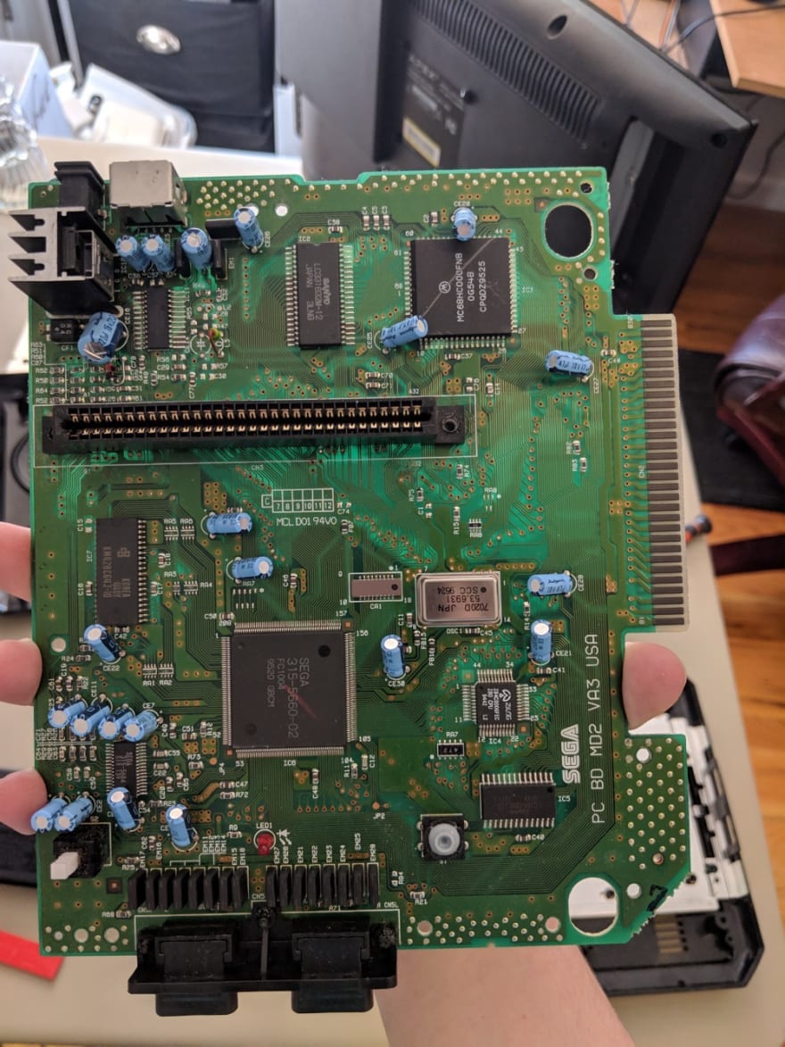
While I kept all of the gear that came with the Sega, including the TV tuner, unfortunately the RF interface is and always has been super finicky. I wasn’t able to get it working in an amount of time that my patience would allow for. I did however take apart the Sega and attempt to diagnose any apparent connector issues (I didn’t find any). Here’s a few photos (note that this is not the “Mega Drive” described in other teardowns):

I went back to taking logic traces of the controller pins and, by some amount of trial and error, figured out what the “Auto/Turbo/Off” (ATO) switches on the controller do. First, visually it’s apparent that one switch is associated with each button on the controller other than the “Start” and “Mode” buttons. I switched each of ATO switches to off and captured the signals pictured below.

In order of activation, the buttons pressed during the trace were: Up, Down, Left, Right, Z, C, X, Y, A, B, Mode, Start. You’ll notice that we don’t have nearly enough pin activations in the trace to account for all of those buttons. What shows up on the trace are the D-pad presses and the B and C buttons, which correspond directly to the pinout described for the stock Sega controller. Clearly, something is up with the missing buttons. But we ignore that for now, and move on to setting all of the ATO switches to Turbo.

Turbo appears to quickly toggle a button as long as it is held down. This might be a great way to get in some quick punches in a fighting game, or float in a game with flying, or any number of other things.

The “Auto” mode of the asciiPad behaves like Turbo except it’s active as long as the button isn’t pressed. Once a button is pressed, the signal for that button is driven high, effectively telling the Sega that the button is currently not being pressed.
The great mystery in all of these traces is why the X, Y, Z, A, Start, and Mode buttons don’t appear to affect the output on the pins at all. I could believe that Mode is perhaps a button that affects the controller operation and does not directly send anything out over the serial line. Similar arguments could be made for the other buttons, e.g. maybe they’re deactivated since a standard Sega controller only supports the A, B, and C buttons. But the A button is standard, and so is Start, and nowhere do we see either appearing in the output. Time to take the controller apart.

Inside the controller, the first thing that’s revealed is the chip that’s doing all of the signals processing for the controller. Beyond that, there really isn’t much to be seen — there’s some resistors and capacitors, but very few, and they’re probably just doing some stuff to the signals coming in from the buttons to the chip. Obviously there is also the header with the colorful wires coming out of it, which gets wrapped up into the black cord and becomes the serial connection to the Sega. The signals routed to that header come directly from the chip.

On the other side, we have the board components that interface with the buttons. For the pressure buttons, when they’re pressed they complete a circuit, which changes the signal that the chips on the other side of the board receives. For the toggle switches, they complete different circuits as they slide into one of three different positions. In the “Off” position, they complete no circuit; in the “Turbo” position they connect with the middle small grey piece, and in the “Auto” position they connect with the outside small grey piece. The exception to this is the “Fast/Slow” toggle, which only has two modes (this switch is located next to the Start and Mode buttons).

When my patience returns, I’ll probably begin again by attempting to get the Sega hooked back up to a TV so I can functionally diagnose any issues with the controller. It’s possible that the buttons that don’t appear to send signals truly aren’t working. It’s an old piece of technology, and it was well used when it was new.
Next up: part 2

Top comments (0)