
Hi everyone, today I thought of making a complete beginner guide to the people who are new to Arduino. In this post I am going to give a detailed description of making a knight rider LED simulation circuit (beginner project) from scratch. For this project I am using an Arduino UNO board.
Well, Arduino is an open-source electronics platform based on easy-to-use hardware and software. Arduino boards are able to read inputs - light on a sensor, a finger on a button, or a Twitter message - and turn it into an output - activating a motor, turning on an LED, publishing something online. You can tell your board what to do by sending a set of instructions to the microcontroller on the board. To do so you use the Arduino programming language (based on Wiring), and the Arduino Software (IDE), based on Processing. Learn more about Arduino and boards visit arduino.cc
As I mentioned earlier I am using an Arduino UNO board for this project. You can buy it online or you can simply simulate the whole project by visiting tinkercad.
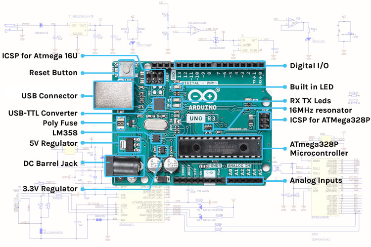
Here is an detailed image of the board
And you need to install the Arduino IDE software to start programing. Download and install it as well.
So now let's get started with the project
Connecting the components together
For this project we need following components
Arduino UNO x1
LED x6
wires
project board x1
connect the components together as shown as below

Writing the program
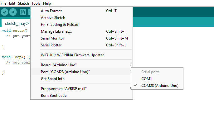
Now that the components are wired together, connect your board to the pc and open Arduino IDE. First make sure that the correct port is selected from the tools.
The Arduino program contains two main parts: setup () and loop (). The name of the functions implies their purpose and activity: setup () sets up the Arduino hardware, such as specifying which I/O lines is planned to use, and whether they are inputs or outputs. The loop () function is repeated endlessly when the Arduino runs.
void setup() {
  // put your setup code here, to run once:

}

void loop() {
  // put your main code here, to run repeatedly:

}
So at first we need to declare our output pins. As the 6 LEDs are connected to the 2-7 digital pins, Let's make them as output using pinMode(). This part goes to the setup().
void setup() {
  pinMode(2,OUTPUT);
  pinMode(3,OUTPUT);
  pinMode(4,OUTPUT);
  pinMode(5,OUTPUT);
  pinMode(6,OUTPUT);
  pinMode(7,OUTPUT);
}
Note :- each line should end with a ";"
To simply this part we can use a For loop as below
{
  for (int i = 2; i <= 7; i++) {
    pinMode(i , OUTPUT);
 }
Now let's think about the output we need. The LEDs should blink like the Knight Rider Car light. Left to right, right to left, on repeat. To accomplish that we need to blink each LED one after other as a line. If we consider 1st LED in the row, at the beginning it needed to be turned on and after few milliseconds needed to be turned off. here's how we do it
digitalWrite(2, HIGH);
delay(100); //interval in milliseconds
digitalWrite(2, LOW);
digitalWrite() method is used to set the pin value to HIGH or LOW, which means toggles the LED. delay() method is used to set the inteval.
Now if we use a For loop to do the same thing to every single LED one after other, we can get the expected output. So the loop() part looks like this.
void loop()
{
  for (int i = 2; i <= 7; i++) {
    digitalWrite(i, HIGH);
    delay(100);
    digitalWrite(i, LOW);
  }

   for (int i = 7; i >= 2; i--) {
    digitalWrite(i, HIGH);
    delay(100);
    digitalWrite(i, LOW);
  }
}
Try to better understand the above code considering the expected output.
Now you can upload the program and see the output.
![]()
Check out the simulation of this on tinkercad.
Thank you. Comment your questions below.

Top comments (0)