
In this blog I will be looking into how to implement live monitoring of water temperature inside the Fish tank where my daughters two goldfish, Goldie and Star, spend their days swimming in. The tank is located next to the desk that I am writing this blog from.
Further background:
My "Office" (aka my daughters bedroom) is located at the front of our house. Our house is north facing, therefore in the morning the sun is on the back of the house and in the afternoon it is on the front where my "Office" is. My "Office has a window that I look out from when I am working from home. In late afternoon the sun especially shines straight in this window (you may see this on some of the YouTube videos that I have done).
The main thing here is the safety of the Fish. They ** must not** be put in direct sunshine, this would heat the water too much and also increase the algae due to the sunlight. So an extra safeguard I typically close the curtains when the sun is very bright or strong. However the ambient temperature of the room still increases and this means the water temperature of the tank also increases. Therefore it would be good to know the water temperature as Goldfish require a range of between 20°C and 23°C.
Hardware:
To measure water temperature you need to invest in some additional components to extend your RaspberryPI. Both a submersible temperature Sensor like the DS18B20 (’https://www.amazon.co.uk/dp/B08HHWD1K9) and a breadboard is essential for this. The DS18B20 is ideal as it has an integrated digital interface where you can read straight from it and you do not need to fiddle with an analog converter.
To setup the hardware you need to do the following:
- Shutdown your Pi and unplug it
- Connect your breadboard to the GPIO on the Pi
- Connect the sensor to the breadboard.
- Start up your Pi
Here is a wiring diagram that helps, thanks to Circuit Basics:
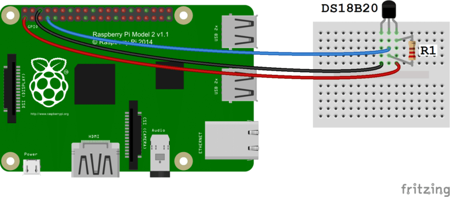
Some tips:
A pull-up resistor of at least 4.7 Ohm is required. This basically allows the sensor's reading to be between a value of 0 and 5 volts and that the digital interface contained within the housing can understand it. The PI then reads this as a temperature from the digital interface. I had to use a resistor from my breadboard kit and this website will help you workout what Ohm is your resistor is https://www.calculator.net/resistor-calculator.html. If you need use a couple of resistors then make sure you wire them in series.
Notice the sensor above comes with a connector at the end. For my first attempt to wire this up, I cut off the connector, then I stripped the wires and tried push them into my breadboard. This was a mistake and did not work. Luckily my breadboard came with a single row pin header. This allowed me to put the row pin header into the board and connector on to the row pin header. Much easier but make sure you place the single row pin header horizontally not vertically.
My final breadboard wiring looked like this:


Turning on and setting up the sensor:
You will need to turn on the digital(one-wire) interface on the PI (GPIO 4). This can be done using the raspi-config.
Select the Interfaces Menu:

Select one-wire:

Turn on one-wire:

Then restart your Pi
Testing
Using cat then we can see if we can read the temperature value straight from the digital interface(one wire). One-wire mounts devices at /sys/bus/w1/devices/. This folder should contain another folder with the name of the UUID of this sensor. This is in case you have more than one and each one would have its own folder. With in the sensor's folder then there is a file called 'temperature' and it contents is the °C value from the sensor.
Here is an example:
ssh pi
Linux raspberrypi 5.10.17-v7+ #1414 SMP Fri Apr 30 13:18:35 BST 2021 armv7l

The programs included with the Debian GNU/Linux system are free software;
the exact distribution terms for each program are described in the
individual files in /usr/share/doc/*/copyright.

Debian GNU/Linux comes with ABSOLUTELY NO WARRANTY, to the extent
permitted by applicable law.
Last login: Sat Apr  2 10:53:44 2022 from 192.168.x.x
pi@raspberrypi:~ $ ls /sys/bus/w1/devices/
28-00000001a7df  w1_bus_master1
pi@raspberrypi:~ $ cat /sys/bus/w1/devices/28-00000001a7df/temperature
20625
pi@raspberrypi:~ $
So that is 20.625c.
Lambda:
In order to get the temperature from the one wire interface into AWS we need to write some custom code. To do this I used a lambda written in Python. The lambda reads the temperature from the interface like any other normal file. The value is then parsed and turned into a JSON object. Then using the publish option in the Greengrass SDK I send the message via an MQTT topic into IoT core. Here is some very important concerns/notes when doing this:
- The lambda needs to be a long running lambda. This basically means it is not a lambda at all. It is in fact a Python app that is deployed via GreenGrass and started when Greengrass starts. It needs a run loop, poll the temperature and publish. Listening to sigterm and sigint
- It needs to run as a container with read access to /sys on the host.
- The Greengrass v2 and v1 way off sending MQTT messages and how a deployment is done is completely different. My code was originally v1 so I had to deploy the LegacySubscriptionRouter with the correct configuration to make it compatible
- I had to do a OTA upgrade of nucleus so that my other components were deployable
Here is the main function executed within the run loop:
def process(iot_client: Client):

    # conh
    sensor_id = os.getenv('TEMP_ID', '28-00000001e2d1')
    path = os.getenv('TEMP_PATH', '/sys/bus/w1/devices/')

    temperature = gettemp(sensor_id, path) / float(1000)
    msg = {
        'sensor_id': sensor_id,
        'temperature': temperature
    }

    send_message(iot_client, msg)

    return msg
This is how to read the temperature:
def gettemp(sensor_id, path):
    try:
        mytemp = ''
        filename = 'w1_slave'
        f = open(path + sensor_id + '/' + filename, 'r')
        line = f.readline()  # read 1st line
        crc = line.rsplit(' ', 1)
        crc = crc[1].replace('\n', '')
        if crc == 'YES':
            line = f.readline()  # read 2nd line
            mytemp = line.rsplit('t=', 1)
        else:
            mytemp = 99999
        f.close()

        return int(mytemp[1])

    except Exception as e:
        LOGGING.exception(e)
        return 99999
This is how to send the message via MQTT (note this is V1 style):
def send_message(iot_client: greengrasssdk.IoTDataPlane.Client, message: dict, topic=TOPIC):

    iot_client.publish(
        topic=topic,
        payload=json.dumps(message).encode("utf-8")
    )
Now if you want to look at code in more detail it is located [https://github.com/philbasford/fishcam] and also note I deployed this using AWS SAM.
IOT Component:
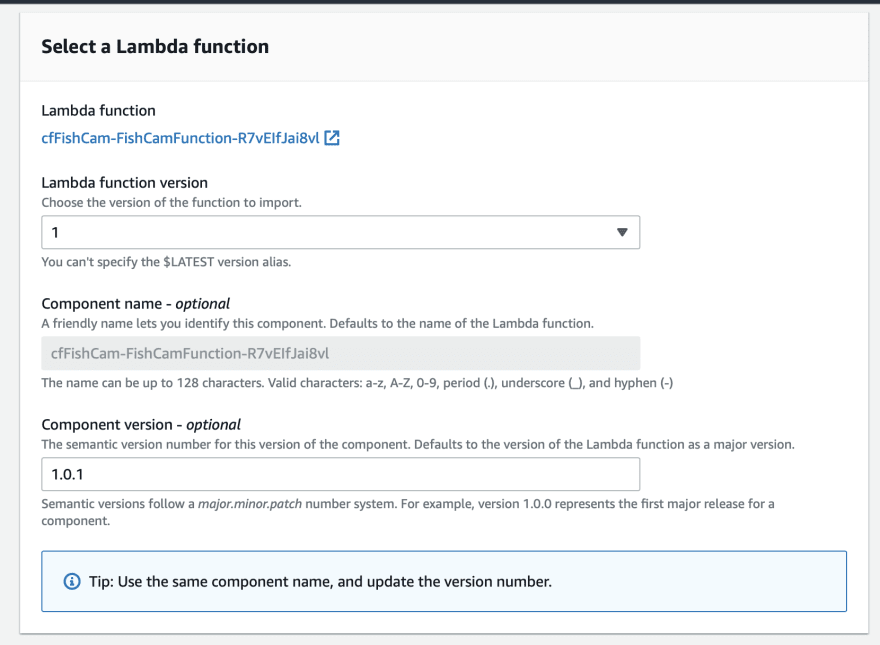
First select the Fish Cam Lambda and use the lambda name and version as the initial component details. However you may need to update the version later if you need to reconfigure.
As mention before one of the most important things is that the lambda is pinned/long running, so that it starts up and down with Greengrass. Also remove any event source:

Make sure you use a container but with access to /sys:

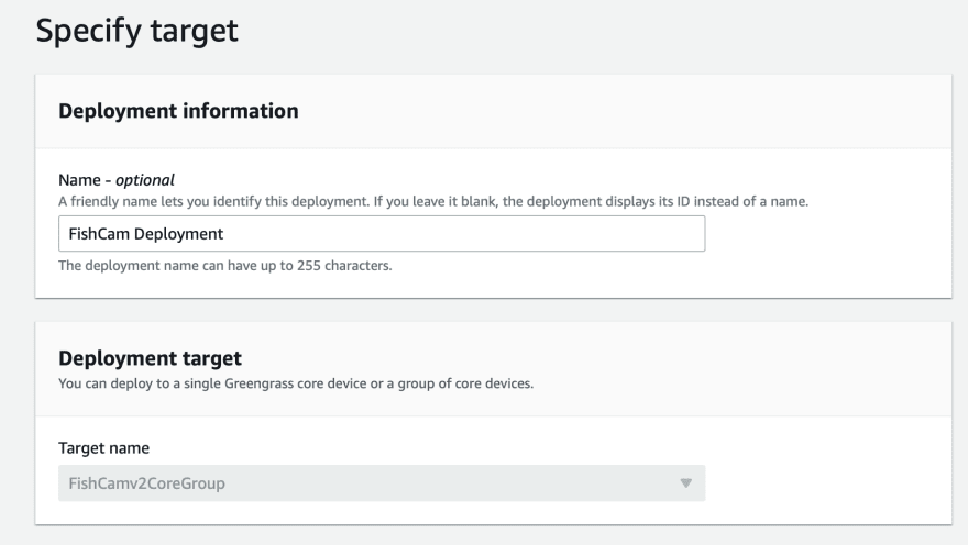
Create IOT Deployment:
Create a new deployment:
Add the Lambda component you created, then the legacy subscription router and nucleus public components.

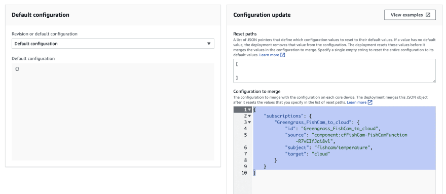
Now go into the legacy subscription router configuration:

Add the following(change the function name to match yours):
{
    "subscriptions": {
        "Greengrass_FishCam_to_cloud": {
            "id": "Greengrass_FishCam_to_cloud",
            "source": "component:cfFishCam-FishCamFunction-R7vEIfJai8vl",
            "subject": "fishcam/temperature",
            "target": "cloud"
        }
    }
}
Then submit it:
Leave the Advance Settings as is:

Then deploy:

Now if it deployed ok, then within the test area of IOT Greengrass section of the AWS Console you should see the messages coming in:

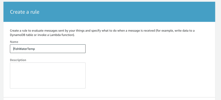
IOT Rule & CloudWatch
To get the messages into CloudWatch you need to create a new rule in the Act area of IOT Greengrass section of the AWS Console:
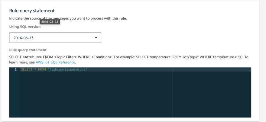
Use a the following SQL to make sure you process all the messages sent to the topic:
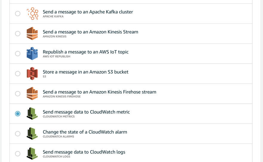
The add action and select CloudWatch Metric:
Then use the following settings with substitutions for the values contain in messages:

Your need a IAM Role and here are the permissions needed:
{
    "Version": "2012-10-17",
    "Statement": {
        "Effect": "Allow",
        "Action": "cloudwatch:PutMetricData",
        "Resource": [
            "*"
        ]
    }
}
Conclusion:
Measuring temperature of the water in the fish tank is really easy, I was able to do this in few hours once I had purchased the additional sensor. It is a good example of how to chain a lot AWS services together to make something useful at low cost.
Here is the final CloudWatch chart for the temperature for a a day, notice the as the sun comes up and goes down the temperature changes:

Thank you and I hope you found this interesting. Next time I will be looking at how to use machine learning to spot fish!

Top comments (0)