
URDF is a custom data format for describing robots. It’s an XML file that provides concepts such as joints, motors and the general dimension of you robot. From this description, you can create and apply simulations. In this article, I will explain how to describe a robot with URDF.
This article is part of a series about simulating and building a robot with the Robot Operating Systems ROS. Read more in the blog series.
This article originally appeared at my blog admantium.com.
Create a Catkin Workspace and Package
All extensions and projects you make in ROS should follow a set of conventions. The topmost convention is to start from a private workspace in which all files will be contained. By issuing commands, this workspace will be available to other ROS packages on your system, and thereby enable the seamless interaction of different packages.
The very first step is to define a private workspace in which we will create the separate ROS packages.
$> mkdir -p ~/ROS/src
$> cd ~/ROS
$> catkin_make
Base path: /home/devcon/ROS
Source space: /home/devcon/ROS/src
...
-- The C compiler identification is GNU 9.3.0
-- The CXX compiler identification is GNU 9.3.0
-- Check for working C compiler: /usr/bin/cc
-- Check for working C compiler: /usr/bin/cc -- works
...
-- Found PythonInterp: /usr/bin/python3 (found suitable version "3.8.5", minimum required is "3")
-- Using PYTHON_EXECUTABLE: /usr/bin/python3
-- Using Debian Python package layout
-- Found PY_em: /usr/lib/python3/dist-packages/em.py
-- Using empy: /usr/lib/python3/dist-packages/e
Then we create the package car-robot inside the directory ROS/src.
$> cd ~/ROS/src
$> catkin_create_pkg car-robot
Created file car-robot/package.xml
Created file car-robot/CMakeLists.txt
Successfully created files in /home/devcon/ROS/car-robot. Please adjust the values in package.xml.
Now that we have the workspace and the package, we can start modelling the robot.
Create the URDF File
In ROS, robots are models with URDF file, a self-contained specification of the robot. It defines the physical structure of the robot, consisting of shapes, links and joints.
Lets create a box shaped robot with four wheels that will look like this:
Create a XML file at urdf/bot.urdf and continue with the next step.
Define the Torso
The structure of a robot is defined with link and joint.
A link is a complex object that describes its static visual properties, its shape as a box, cylinder or sphere, and its materials with color or textures.
The robots' torso is a box, expressed in URDF like this:
<?xml version="1.0"?>
<robot name="bot">
  <link>
    <visual>
      <geometry>
        <box />
      </geometry>
    </visual>
  </link>
</robot>
The size parameters define its x-y-z coordinates in meter. Then we define its color as green, using RGB values.
<?xml version="1.0"?>
<robot name="bot">
  <link name="torso">
    <visual>
      <geometry>
        <box size="0.6 0.3 0.1"/>
      </geometry>
      <material name="green">
        <color rgba="1.0 1.0 0.0 1"/>
      </material>
    </visual>
  </link>
</robot>
So far, so good. Let’s check that the URDF file is correct.
$> check_urdf urdf/bot.urdf

robot name is: car-bot
---------- Successfully Parsed XML ---------------
root Link: torso has 0 child(ren)
Before we continue, we need to learn about another ROS convention. The base_link element that represents the central element of the robot, the root of the tree structure defined in the URDF file. Define this element, and connect it to the torso.
<link name="base_link">
  <visual>
    <geometry>
      <box size="0 0 0"/>
    </geometry>
    <material name="red">
      <color rgba="1 0 0 1"/>
    </material>
  </visual>
</link>

<joint name="base_link_torso" type="continuous">
  <parent link="base_link" />
  <child link="torso" />
  <origin xyz="0 0 0" rpy="0 0 0"/>
</joint>
Then we can render the torso with the tool rviz, and see this:

Add the Wheels
The robot will have four wheels, positioned at the sides of the box. Wheels are drawn as cylinder, with attributes radius and link. To separate them from the torso, they will be painted red.
The URDF declaration is this:
<link name="left_wheel">
  <visual>
    <geometry>
      <cylinder radius="0.04" length="0.05" />
    </geometry>
    <material name="red">
      <color rgba="1 0 0 1"/>
    </material>
  </visual>
</link>

<link name="right_wheel">
  <visual>
    <geometry>
      <cylinder radius="0.04" length="0.05" />
    </geometry>
    <material name="red">
      <color rgba="1 0 0 1"/>
    </material>
  </visual>
</link>
However, we cannot render the robot with just these declarations. We need to express the relationships between all robot parts using joints.
Joints define parent-child relationships of other elements in an URDF file. They also enable the positioning of the elements: With origin, the relative offset from its parents is defined, and the optional axis declaration expresses the rotation of revolute or prismatic joints.
Let start simple with the right wheel. The URDF declaration is as follows:
<joint name="base_link_right_wheel" type="continuous">
  <parent link="base_link" />
  <child link="right_wheel" />
  <origin xyz="0.2 -0.2 -0.05" rpy="1.570796  0 0"/>
</joint>
The and tags reference the links we created earlier. The origin positions the child relative to its parent. Here, the xyz attribute controls the position in the 3D cartesian space. The rpy value controls the 'tilt' of the object.
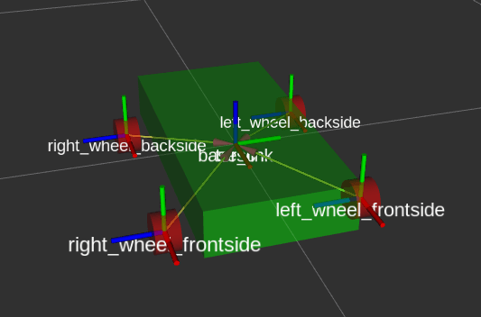
Take a look at the this picture:

In this picture, the right wheel is defined as rpy="0 0 0" - it’s basically lying flat. The left wheel has an rpy="1.570796 0 0", which means that we roll it around the x-axis by value is pi/2. It is perfectly aligned with the torso.
With this knowledge, we can produce the following alignment:
<joint name="base_link_left_wheel" type="continuous">
  <axis xyz="0.0 0.0 1" />
  <parent link="base_link" />
  <child link="left_wheel" />
  <origin xyz="1.5 0 0" rpy="-1.5 0 0" />
</joint>

<joint name="base_link_right_wheel" type="continuous">
  <axis xyz="0.0 0.0 1" />
  <parent link="base_link" />
  <child link="right_wheel" />
  <origin xyz="-1.5 0 0" rpy="-1.5 0 0" />
</joint>
Which is rendered as this:
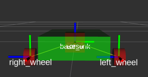
Now both wheels are aligned correctly. Let’s add the definitions of the back wheels.
<link name="left_wheel_backside">
    <visual>
      <geometry>
        <cylinder radius="0.04" length="0.05" />
      </geometry>
      <material name="red">
        <color rgba="1 0 0 1"/>
      </material>
    </visual>
  </link>

  <joint name="base_link_left_wheel_backside" type="continuous">
    <parent link="base_link" />
    <child link="left_wheel_backside" />
    <origin xyz="-0.2 0.2 -0.05" rpy="1.570796 0 0"/>
  </joint>

  <link name="right_wheel_frontside">
    <visual>
      <geometry>
        <cylinder radius="0.04" length="0.05" />
      </geometry>
      <material name="red">
        <color rgba="1 0 0 1"/>
      </material>
    </visual>
  </link>

  <joint name="base_link_right_wheel_frontside" type="continuous">
    <parent link="base_link" />
    <child link="right_wheel_frontside" />
    <origin xyz="0.2 -0.2 -0.05" rpy="1.570796  0 0"/>
  </joint>

   <link name="right_wheel_backside">
    <visual>
      <geometry>
        <cylinder radius="0.04" length="0.05" />
      </geometry>
      <material name="red">
        <color rgba="1 0 0 1"/>
      </material>
    </visual>
  </link>
and see the final result.
Conclusion
This article showed the essential steps to define a ROS URDF model. We learned about the core XML tags that make up an URDF file: <link> that defines structures, with a <geometry> property to represent boxes, cylinders or spheres. These shapes can be given colors or even textures. These structures need to be connected by <joints>, forming a parent-child relationship. The <joints> also position the shapes to each other: defining how to align them along their axis, and where their origin is.
The final file is verbose and contains a lot of repetitive expressions. In the next article, we will see how to utilize the Xarco XML macro format to provide a better readable and manageable representation of our robot.

Top comments (0)