Introduction
In the last analysis, we explored various aspects of assembly codes running in 6502 processor. Today, we will continue on the journey by experimenting with the same code we previously used.
Code:
        lda #$00    ; set a pointer at $40 to point to $0200
        sta $40
        lda #$02
        sta $41

        lda #$07    ; colour number

        ldy #$00    ; set index to 0

loop:   sta ($40),y ; set pixel at the address (pointer)+Y

        iny         ; increment index
        bne loop    ; continue until done the page

        inc $41     ; increment the page
        ldx $41     ; get the current page number
        cpx #$06    ; compare with 6
        bne loop    ; continue until done all pages
Experiments
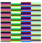
1. Adding tya instruction after loop: and before sta ($40), y

As we can see, the screen shows 16 different colors repeating twice in 32 x 32 pixel bitmapped display. This result is not surprising once we know what tya instruction does. The tya stands for "transfer Y to accumulator". Since the emulator screen can only display 16 different colors with the lowest four bits of each byte and the screen size is 32 x 32, the color must change every time the y gets incremented but is limited to 16 different options.
2. Adding lsr instruction after tya

Interestingly, adding lsr instruction after tya causes each color to take two pixels instead of one, which results in 16 different colors displayed in each row. What lsr instruction does is to do logical shift right on the byte stored in the accumulator. As doing logical shift right makes the least significant bit to be lost and 0 is added on the other end, the hexadecimal value of 01 (0001) gets converted into 00 (0000) whereas the hexadecimal value of 00 (0000) stays as 00 (0000). Ultimately, the same pattern repeats for each byte which makes each color to take 2 pixels in a row.
3. Repeating lsr instruction after tya for multiple times
As we discovered before, adding lsr instruction causes each color to display in two pixels instead of one. So, what would happen if we repeat this multiple times?

As we can see above, adding another lsr instruction makes each color to take pixel twice as large as before. How about adding one more lsr again?
Not surprisingly, adding one more lsr instruction causes each color to take 8 pixels which is twice as large as the previous code. If we follow this logic, we can make one color to take the whole row (= 32 pixels) by repeating it five times.

3. Adding asl instruction after tya instead of lsr
What would happen if we use logical shift left? In contrast to lsr, asl instruction shifts one bit to the left. Doing so results in the following image:

Doing logical shift left causes the most significant bit to be discarded and a zero bit is inserted on the other end. For example, the hexadecimal value of 01 (0001) gets converted to 02 (0010). This is equivalent of doing multiply-by-two and we lose some of the colors to be displayed on the screen (16 colors -> 8 colors).
Thus, adding another asl instruction would cause the number of colors to be halved as follows:

4. Adding multiple instances of iny instructions
Let's get back to the original code and include multiple iny instructions this time. Having even number of iny seems to create a gap between colored pixel as shown below:
Code:
        lda #$00    ; set a pointer at $40 to point to $0200
        sta $40
        lda #$02
        sta $41

        lda #$07    ; colour number

        ldy #$00    ; set index to 0

loop:   sta ($40),y ; set pixel at the address (pointer)+Y

        iny         ; increment index
        iny         ; increment index
        iny         ; increment index
        iny         ; increment index
        bne loop    ; continue until done the page

        inc $41     ; increment the page
        ldx $41     ; get the current page number
        cpx #$06    ; compare with 6
        bne loop    ; continue until done all pages
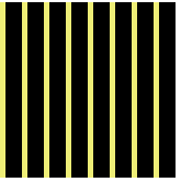
This makes sense if we think carefully. Since we increment y inside the loop even number of times, we leave bytes untouched and have the hexadecimal value of 00 which results in black color.
Interestingly, if we use an odd number of iny, the screen shows the 32 x 32 pixel bitmapped screen filled with the color just like the original code but with a checkboard animation. Why does this happen?

This is because the loop does not stop as y increments in odd number and the zero flag does not turn on (when the y index value reaches zero). The loop continues on until each pixel is filled in the entire page.
5. Making use of pseudo-random number generator at $fe
The emulator stores a one byte pseudo-random number generator at the address of $fe. With this we can generate a screen filled with randomized colors in each pixel.
Code:
        lda #$00    ; set a pointer at $40 to point to $0200
        sta $40
        lda #$02
        sta $41

        lda $fe ; pseudo-random number generator

        ldy #$00    ; set index to 0

loop:   sta ($40),y ; set pixel at the address (pointer)+Y

        iny         ; increment index
        bne loop    ; continue until done the page

        lda $fe     ; pseudo-random number generator
        inc $41     ; increment the page
        ldx $41     ; get the current page number
        cpx #$06    ; compare with 6
        bne loop    ; continue until done all pages

Conclusion
In this post, we experimented with different instructions to see how they affected the display of the emulator. It is interesting know that even small change of the code can drastically change the way of displaying pixels.


Top comments (0)