In my last post I translated BAL commands into control signals for the BPU. It's now time to implement the logic generating these signals and all the parts will be ready to be put together.
Recap
Last time on Esoposting
In the previous episode I came up with the following list of translations from BAL commands to BPU signals:
Every command
0. PC->A; MEM->D; D->PR;

+/-
1. DP->A; MEM->D; D->ALU; PC++;
2. DP->A; ALU->D; D->MEM;

>/<
1. DP->D; D->ALU; PC++;
2. ALU->D; D->DP;

[/]
1. PC->D; D->ALU; PC++;
2. DP->A; ALU->D; D->PC;

,
1. DP->A; I/O; D->MEM; PC++;
2. Next Command;

.
1. DP->A; MEM->D; I/O; PC++;
2. Next Command;
Commands run for three clock cycles except for I/O commands that run for two cycles and will need a "Next Command" signal to immediately reset the cycle counter to 0.
Cycle counter
Command Decoder abstract
As shown above the Command Decoder needs to keep track of clock cycles to create correct signal combination. This could be achieved using a 2-bit counter, but I prefer to use a 2-bit shift register. It's a type of register that moves its contents one bit to the right every clock cycle, discarding the rightmost bit and taking the new leftmost bit from input.
This solution is almost identical (just mirrored) to the counter for 3-cycle commands: 00 on cycle 0, 10 on cycle 1 and 01 on cycle 2. The advantage of the shift register is that if for any reason the cycle continues past these two states, the counter enters its fourth state: 11, while the shift register resets back to 00 by itself making it a bit safer and easier to wire up.

The shift input of the register should be 1 when the register is at 00 to make the transition 00 -> 10 and 0 at other times, which can be accomplished by taking a NOR of the registers contents and the Load signal. This NOR output also indicates the 0th cycle, so the Load signal is here to disable it when loading.
The other register input that I care about is "reset". There are three situations where the cycle count should reset: when the whole machine is reset, on the third cycle of I/O commands and when loading data from ROM. Signals regarding each of these instances should be ORed together for the "reset" input of the register.
The register also needs to connect to the clock for synchronisation. Usually it's as simple as connecting a wire to an input, but here it requires a twist. The signals generated by the command decoder govern the data flow inside the BPU. Nothing in electronics can happen in the same instant. Because of physical constraints every action happening in the computer can get delayed by several nanoseconds. If data transfer is designed to happen at the same time as the control signal change then some actions will take place with the old control signals in place while other will act according to the new signals, resulting in a wrong action and breaking the system. To prevent that, the clock signal is inverted inside the command decoder. This means command change happens at the falling edge of the clock while data transfer happens on the rising edge, ensuring that nothing breaks.
Decoding the signals
What we came here for
With the cycle counter done I have all inputs necessary to decode the signals. Each signal is a simple boolean function of the command and the cycle count. I will start each signal with a table indicating at which inputs it should be on (1), when it should be off (0) and when it doesn't matter (-). In these tables the BAL commands will be listed in an unconventional way, such that binary representations of neighbouring commands vary only by one bit. It makes it easier to create boolean functions based on these tables.
| Command | + |
- |
< |
> |
, |
. |
] |
[ |
|---|---|---|---|---|---|---|---|---|
| Decimal | 0 | 1 | 3 | 2 | 6 | 7 | 5 | 4 |
| Binary | 000 |
001 |
011 |
010 |
110 |
111 |
101 |
100 |
D->ALU
| T | + |
- |
< |
> |
, |
. |
] |
[ |
|---|---|---|---|---|---|---|---|---|
000 |
001 |
011 |
010 |
110 |
111 |
101 |
100 |
|
| 0 | - |
- |
- |
- |
- |
- |
- |
- |
| 1 | 1 |
1 |
1 |
1 |
- |
- |
1 |
1 |
| 2 | - |
- |
- |
- |
- |
- |
- |
- |
| L | - |
- |
- |
- |
- |
- |
- |
- |
Because ALU never stores data over more than one clock cycle it doesn't matter if it takes value from the bus or not, unless it's required to perform addition. The D->ALU signal can be just tied high all the time.
D->ALU = 1

ALU->D
| T | + |
- |
< |
> |
, |
. |
] |
[ |
|---|---|---|---|---|---|---|---|---|
000 |
001 |
011 |
010 |
110 |
111 |
101 |
100 |
|
| 0 | 0 |
0 |
0 |
0 |
0 |
0 |
0 |
0 |
| 1 | 0 |
0 |
0 |
0 |
0 |
0 |
0 |
0 |
| 2 | 1 |
1 |
1 |
1 |
- |
- |
1 |
1 |
| L | 0 |
0 |
0 |
0 |
0 |
0 |
0 |
0 |
Unlike D->ALU this signal puts data on the Data Bus, so it has a lot of restrictions on when it can't be high. Fortunately, because the second cycle on I/O commands doesn't exist, this arrangement of ones allows to connect the signal directly to the second cycle.
ALU->D = T2

D->PR
| T | + |
- |
< |
> |
, |
. |
] |
[ |
|---|---|---|---|---|---|---|---|---|
000 |
001 |
011 |
010 |
110 |
111 |
101 |
100 |
|
| 0 | 1 |
1 |
1 |
1 |
1 |
1 |
1 |
1 |
| 1 | 0 |
0 |
0 |
0 |
0 |
0 |
0 |
0 |
| 2 | 0 |
0 |
0 |
0 |
- |
- |
0 |
0 |
| L | - |
- |
- |
- |
- |
- |
- |
- |
The Program Register is updated with a new command on each zeroth cycle, which means it can be directly connected to it.
D->PR = T0

MEM->D
| T | + |
- |
< |
> |
, |
. |
] |
[ |
|---|---|---|---|---|---|---|---|---|
000 |
001 |
011 |
010 |
110 |
111 |
101 |
100 |
|
| 0 | 1 |
1 |
1 |
1 |
1 |
1 |
1 |
1 |
| 1 | 1 |
1 |
0 |
0 |
0 |
1 |
0 |
0 |
| 2 | 0 |
0 |
0 |
0 |
- |
- |
0 |
0 |
| L | 0 |
0 |
0 |
0 |
0 |
0 |
0 |
0 |
This signal is a bit more complicated. Not only it should be on during the zeroth cycle but also on the first cycle for add, subtract and output commands.
MEM->D = T0 OR (T1 AND ~C0 AND ~C1) OR (T1 AND C0 AND C1 AND ~C2)

D->MEM
| T | + |
- |
< |
> |
, |
. |
] |
[ |
|---|---|---|---|---|---|---|---|---|
000 |
001 |
011 |
010 |
110 |
111 |
101 |
100 |
|
| 0 | - |
- |
- |
- |
- |
- |
- |
- |
| 1 | - |
- |
0 |
0 |
1 |
- |
0 |
0 |
| 2 | 1 |
1 |
0 |
0 |
- |
- |
0 |
0 |
| L | 1 |
1 |
1 |
1 |
1 |
1 |
1 |
1 |
This signal only has to be on during the second cycle of the add/sub commands, the first cycle of the input command and during loading, but it can also be on whenever MEM->D is on overwriting the data in the memory with itself. Using some of those - fields as ones allows for much simpler functions.
D->MEM = L OR (~C0 AND ~C1) OR (C0 AND C1)

DP->D
| T | + |
- |
< |
> |
, |
. |
] |
[ |
|---|---|---|---|---|---|---|---|---|
000 |
001 |
011 |
010 |
110 |
111 |
101 |
100 |
|
| 0 | 0 |
0 |
0 |
0 |
0 |
0 |
0 |
0 |
| 1 | 0 |
0 |
1 |
1 |
0 |
0 |
0 |
0 |
| 2 | 0 |
0 |
0 |
0 |
- |
- |
0 |
0 |
| 0 | 0 |
0 |
0 |
0 |
0 |
0 |
0 |
0 |
As another signal that outputs data onto the Data Bus DP->D has a very strict table with no -. It can only be on during the first cycle of the pointer moving commands.
DP->D = T1 AND ~C0 AND C1

D->DP
| T | + |
- |
< |
> |
, |
. |
] |
[ |
|---|---|---|---|---|---|---|---|---|
000 |
001 |
011 |
010 |
110 |
111 |
101 |
100 |
|
| 0 | 0 |
0 |
0 |
0 |
0 |
0 |
0 |
0 |
| 1 | 0 |
0 |
- |
- |
0 |
0 |
0 |
0 |
| 2 | 0 |
0 |
1 |
1 |
- |
- |
0 |
0 |
| L | 0 |
0 |
0 |
0 |
0 |
0 |
0 |
0 |
As with D->MEM, D->DP can be on when DP->D is on, but it doesn't help much in this case. The - in the I/O commands on the other hand help minimise this function. The smallest function is when D->DP is on during the second cycle of the pointer moving commands and I/O commands, because the latter never occurs.
D->DP = T2 AND C1

DP->A
| T | + |
- |
< |
> |
, |
. |
] |
[ |
|---|---|---|---|---|---|---|---|---|
000 |
001 |
011 |
010 |
110 |
111 |
101 |
100 |
|
| 0 | 0 |
0 |
0 |
0 |
0 |
0 |
0 |
0 |
| 1 | 1 |
1 |
- |
- |
1 |
1 |
- |
- |
| 2 | 1 |
1 |
- |
- |
- |
- |
1 |
1 |
| L | 0 |
0 |
0 |
0 |
0 |
0 |
0 |
0 |
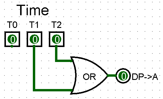
There are only two signals that output to the Address Bus: DP->A and PC->A, which means that whenever one is off the other can
be on. This leads to the simplest solution: PC->A is on during loading and the zeroth cycle, and DP->A is on during first and second cycles.
DP->A = T1 OR T2
PC->D
| T | + |
- |
< |
> |
, |
. |
] |
[ |
|---|---|---|---|---|---|---|---|---|
000 |
001 |
011 |
010 |
110 |
111 |
101 |
100 |
|
| 0 | 0 |
0 |
0 |
0 |
0 |
0 |
0 |
0 |
| 1 | 0 |
0 |
0 |
0 |
0 |
0 |
1 |
1 |
| 2 | 0 |
0 |
0 |
0 |
- |
- |
0 |
0 |
| 0 | 0 |
0 |
0 |
0 |
0 |
0 |
0 |
0 |
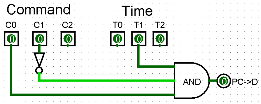
Analogous to DP->D.
PC->D = T1 AND C0 AND ~C1
D->PC
| T | + |
- |
< |
> |
, |
. |
] |
[ |
|---|---|---|---|---|---|---|---|---|
000 |
001 |
011 |
010 |
110 |
111 |
101 |
100 |
|
| 0 | 0 |
0 |
0 |
0 |
0 |
0 |
0 |
0 |
| 1 | 0 |
0 |
0 |
0 |
0 |
0 |
- |
- |
| 2 | 0 |
0 |
0 |
0 |
- |
- |
1 |
1 |
| L | 0 |
0 |
0 |
0 |
0 |
0 |
0 |
0 |
Analogous to D->DP
D->PC = T2 AND C0

PC->A
| T | + |
- |
< |
> |
, |
. |
] |
[ |
|---|---|---|---|---|---|---|---|---|
000 |
001 |
011 |
010 |
110 |
111 |
101 |
100 |
|
| 0 | 1 |
1 |
1 |
1 |
1 |
1 |
1 |
1 |
| 1 | 0 |
0 |
0 |
0 |
0 |
0 |
0 |
0 |
| 2 | 0 |
0 |
0 |
0 |
- |
- |
0 |
0 |
| L | 1 |
1 |
1 |
1 |
1 |
1 |
1 |
1 |
PC->A function is very simple because it's only on during loading and the zeroth cycle.
PC->A = T0 OR L

PC++
| T | + |
- |
< |
> |
, |
. |
] |
[ |
|---|---|---|---|---|---|---|---|---|
000 |
001 |
011 |
010 |
110 |
111 |
101 |
100 |
|
| 0 | 0 |
0 |
0 |
0 |
0 |
0 |
0 |
0 |
| 1 | 1 |
1 |
1 |
1 |
1 |
1 |
1 |
1 |
| 2 | 0 |
0 |
0 |
0 |
- |
- |
0 |
0 |
| L | 1 |
1 |
1 |
1 |
1 |
1 |
1 |
1 |
PC++ function is similar to PC->A but instead of being on during the zeroth cycle it's on during the first cycle.
PC++ = T1 OR L

I/O
| T | + |
- |
< |
> |
, |
. |
] |
[ |
|---|---|---|---|---|---|---|---|---|
000 |
001 |
011 |
010 |
110 |
111 |
101 |
100 |
|
| 0 | 0 |
0 |
0 |
0 |
0 |
0 |
0 |
0 |
| 1 | 0 |
0 |
0 |
0 |
1 |
1 |
0 |
0 |
| 2 | 0 |
0 |
0 |
0 |
- |
- |
0 |
0 |
| L | 0 |
0 |
0 |
0 |
0 |
0 |
0 |
0 |
The I/O signal is one of the two signals that act immediately when they are turned on: it stops the BPU until the input/output circuit confirms it's ready to perform the operation. This means it can't be on during any other time than the first cycle of I/O commands, except for the nonexistent second cycle of I/O which doesn't help minimise the function.
I/O = T1 AND C0 AND C1

Next Command
| T | + |
- |
< |
> |
, |
. |
] |
[ |
|---|---|---|---|---|---|---|---|---|
000 |
001 |
011 |
010 |
110 |
111 |
101 |
100 |
|
| 0 | 0 |
0 |
0 |
0 |
0 |
0 |
0 |
0 |
| 1 | 0 |
0 |
0 |
0 |
0 |
0 |
0 |
0 |
| 2 | 0 |
0 |
0 |
0 |
1 |
1 |
0 |
0 |
| L | - |
- |
- |
- |
- |
- |
- |
- |
The Next Command signal is used to reset the Cycle Counter on the second cycle of I/O commands. It acts by immediately setting the counter to 0 as soon as it's on which prevents it from advancing if it was set at cycle 0. It is free to be on during loading because the counter is reset at that moment anyway. This doesnt't help minimise its function, though.
Next Command = T2 AND C0 AND C1

Conclusion
Almost done!
After putting together all circuits designed in today's tutorial the resulting Command Decoder doesn't fit on the screen, but you can always see and tinker with it by downloading it from the github repo. With the final BPU part done next articles will be about connecting everything together and adding some minor circuits and testing, so we're on a home stretch now. Feel free to leave any feedback you have in the comments and see you next time!


Top comments (0)