This is a tutorial on drawing styled rectangles using Metal graphics shaders. Learn how to draw a rectangle, add borders, round the rectangle’s corners, and fill the rectangle with linear gradients.
Why render on the GPU
For apps that require fast rendering, such as video processing apps or 3D game apps, using the GPU for rendering is often required. The GPU has more cores and so can perform data-parallel calculations like calculating pixel position and color very quickly.
The tradeoff of using the GPU is that we have to implement shaders. However, for a modern UI app, you'd only have to implement them for glyphs, icons, and rectangles. Warp's UI, for example, is entirely composed of those three primitives.

This tutorial will focus just on shaders for rectangles. The snack bar, centered at the top of the window, is just a rectangle with a border and rounded corners.
We will walk through drawing a rectangle, adding borders, rounding the rectangle’s corners, and filling the rectangle with a linear gradient. We will cover interesting graphics concepts like distance fields, vector projections, and antialiasing.
This tutorial is aimed at beginners who are new to GPU rendering. The code examples are in Metal, Apple’s official shader API.
Here is the table of contents: you can feel free to jump to any section.
- Why render on the GPU
- How to draw a basic rectangle using shaders
- How to draw borders on a rectangle using shaders
- How to draw rounded rectangles using shaders
- How to fill rectangles with gradients using shaders
- Putting it all together
How to draw a basic rectangle using shaders
We provide instructions to the GPU via a pair of functions: the vertex shader and the fragment shader. The vertex shader’s job is to produce the positions that need to be drawn. The fragment shader takes these positions and determines the color for every pixel within these position boundaries. In the case of a triangle, the vertex shader produces the three vertices, and the fragment shader fills the triangle pixel by pixel.
)](https://res.cloudinary.com/practicaldev/image/fetch/s--tfy-NGlM--/c_limit%2Cf_auto%2Cfl_progressive%2Cq_auto%2Cw_880/https://dev-to-uploads.s3.amazonaws.com/uploads/articles/c9bwd7hib8inqlc2wfz1.png)
Let’s draw a rectangle with shaders.
For the vertex shader, we normalize the coordinates of the vertex to be independent of the viewport. Concretely, we do this by dividing the coordinates by half of the viewport (see the diagram above from these Apple Metal docs).
For the fragment shader, we can return the interpolated color of the pixel.
Here is the code we’re using. Notice that we also pass in PerRectUniforms—a struct that holds the origin, size, and color information of the rectangle the vertex comes from. This information helps us infer information about each vertex and calculate the color of each pixel.
rect_vertex_shader(
   uint vertex_id [[vertex_id]],
   constant vector_float2 *vertices [[buffer(0)]],
   constant PerRectUniforms *rect_uniforms [[buffer(1)]],
   constant Uniforms *uniforms [[buffer(2)]]
) {
   float2 pixel_space_position = vertices[vertex_id] * rect_uniforms->size + rect_uniforms->origin;
   vector_float2 viewport_size = uniforms->viewport_size;

   RectFragmentData out;
   out.position = vector_float4(0.0, 0.0, 0.0, 1.0);
// Normalize coordinates of the vertex
   out.position.xy = pixel_space_position / (viewport_size / 2.0);
   out.position.z = rect_uniforms->z_index / uniforms->max_z_index;
   out.color = rect_uniforms->background_color;

   return out;
}

fragment float4 rect_fragment_shader(RectFragmentData in [[stage_in]])
{
   return in.color;
}
For brevity, we’ll focus only on writing the shaders for the rendering pipeline. We recommend:
- Apple’s ‘Using Metal to Draw a View’s Content’ to learn how to use MetalKit to create a view and send rendering commands to draw on it
- Apple’s ‘Using a Render Pipeline to Render Primitives’ explains how to use the shaders in the rendering commands to draw a shape on the view.
We used the code above, along with MetalKit and our custom layout engine, to draw the first iteration of tabs in Warp.

How to draw borders on a rectangle using shaders
While drawing borders, the rectangle stays the same size and shape. Hence, we do not need to alter our vertex shader. Instead, we just have to edit the fragment shader.
The fragment shader processes a pixel at a time. For each pixel, we have to figure out whether it is inside or outside the border. First, we calculate the border boundary by subtracting the border widths corresponding to the pixel’s quadrant. If the pixel is above and to the right of the center of the rectangle, then we should subtract the rectangle corner by the border top and the border bottom.
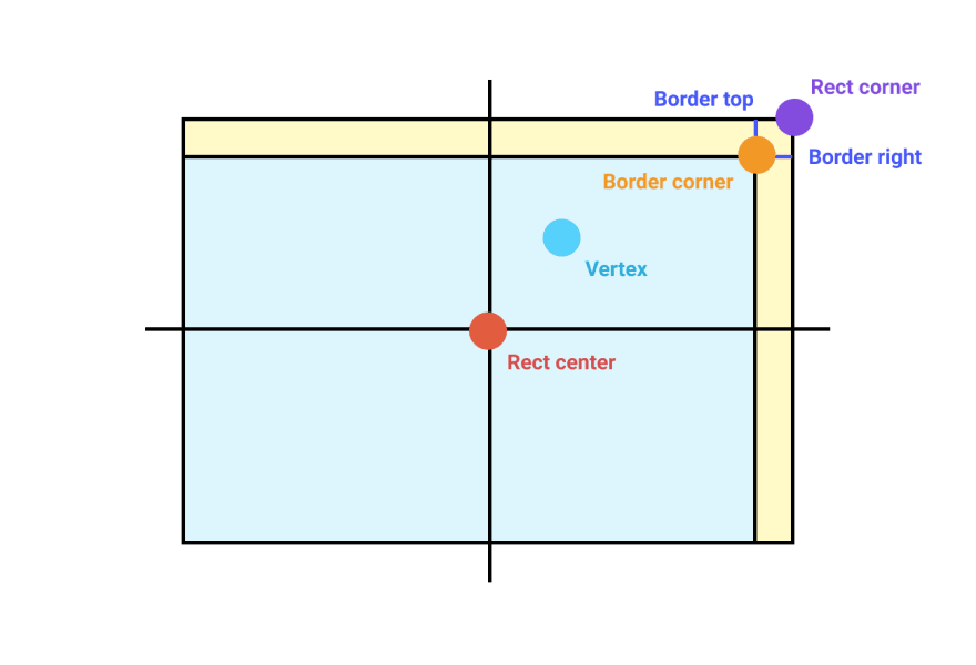
And so on and so forth:
fragment float4 rect_fragment_shader(
       RectFragmentData in [[stage_in]],
constant Uniforms *uniforms [[buffer(0)]])
{
   vector_float2 border_corner = in.rect_corner;
   if (in.position.y >= in.rect_center.y) {
       border_corner.y -= in.border_bottom;
   } else {
       border_corner.y -= in.border_top;
   }
   if (in.position.x >= in.rect_center.x) {
       border_corner.x -= in.border_right;
   } else {
       border_corner.x -= in.border_left;
   }
   ...

}
With the border corner obtained, we can then assign pixels outside the border corner with the border color, the ones inside with the background color.
...
return in.position.xy > border_corner ? border_color : background_color;
And that’s how we form the bordered rectangle in Warp’s tab bar:
![]()
How to draw rounded rectangles using shaders
To round the corners of the rectangle, we need a framework that tells the the fragment shader whether a pixel falls inside or outside a rounded edge.
Distance fields are functions that help us define non-rectangular edges. Given a pixel, a distance field outputs its distance to the nearest edge of a shape. This is a useful API for fragment shaders, which only has access to one pixel at a time.
Using distance fields to express rounded corners
The following diagram draws out four distance fields of a rectangle (lines). Each line represents pixels that are the same distance away from the edge of a rectangle, similar to contour maps in geography. Notice that each distance field matches the outline of rounded rectangles.
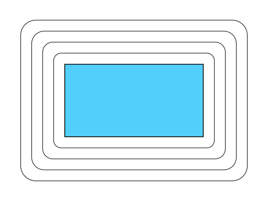
A rounded rectangle is simply a union of a “shrunk rectangle” and the area within the distance field of size corner_radius.
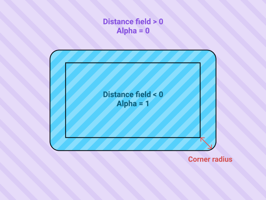
We derive the new rectangle corner of the shrunk rectangle by subtracting the corner radius from the original rectangle corner. We want pixels outside the shape to be transparent, i.e. for the alpha channel of its color to be 0. And pixels inside to be opaque, i.e. alpha = 1.
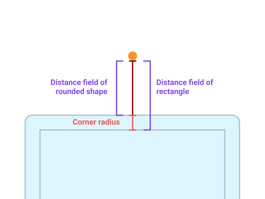
The distance field of our rounded shape is simply the distance field of the shrunk rectangle minus the corner radius.
The formula for distance field of a rectangle is:
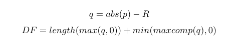
Where p is the vector of the pixel, and R is the vector of the rectangle corner. Check out Inigo Quilez’s derivation of the distance field function here.
The actual R of the shrunk rectangle is rect_corner-corner_radius. Substituting that in gives us a distance function for the shrunk rectangle. We then get the distance function for the rounded rectangle by subtracting the corner radius.
float distance_from_rect(vector_float2 pixel_pos, vector_float2 rect_center, vector_float2 rect_corner, float corner_radius) {
   vector_float2 p = pixel_pos - rect_center;
   vector_float2 q = abs(p) - (rect_corner - corner_radius);
   return length(max(q, 0.0)) + min(max(q.x, q.y), 0.0) - corner_radius;
}
Anti-aliasing
The code above will render a rectangle with rounded corners. However, the rounded edges will look jagged:
 From learnopengl.com
This happens because there is a sharp cutoff between the pixels inside the shape and outside the shape. We only encounter this issue now because with rounded corners, the edges of our shape do not fit squarely into the pixel grid of a screen. The solution is to gradually transition the pixel color across the boundary. A handy function is smoothstep(edge0, edge1, x) which performs a smooth Hermite interpolation between 0 and 1 when edge 0 < x < edge1.
if (corner_radius > 0) {
   color.a *= 1.0 - smoothstep(-0.75, -0.1, shape_distance);
}
For rounded rectangles with borders, we perform the same antialiasing between the background and border. Here in this code, background_distance refers to the distance field from the non-border contents of the rectangle.
background_distance = distance_from_rect(in.position.xy, in.rect_center, border_corner, corner_radius);
if (border_color.a != 0) {
   color = mix(background_color, border_color, smoothstep(-0.5, 0.5, background_distance));
}
Now, we can render rounded bordered UIs like in Warp:
![]()
How to fill rectangles with gradients using shaders
Linear gradients can be specified by a start and end color, as well as the starting coordinates and the ending coordinates. For example, we can specify a horizontal gradient using (0,0) and (0,1) as coordinates.
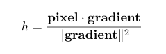
We can perform the mixing of the colors with Metal’s mix function: mix(start_color, end_color, h). It returns the linear blend of start_color + (end_color – start_color) * h.
We want the variable h to represent the progression of the pixels along the direction of the gradient. To do so, the trick is to project the position of the pixel to the direction of the gradient. Pixels closer to the end of the gradient will have a larger magnitude and pixels closer to the start of the gradient will have a smaller magnitude.
float4 derive_color(float2 pixel_pos, float2 start, float2 end, float4 start_color, float4 end_color) {
   float2 adjusted_end = end - start;
   float h = dot(pixel_pos - start, adjusted_end) / dot(adjusted_end, adjusted_end);
   return mix(start_color, end_color, h);
}
We can now produce gradient UI elements, like this header in Warp:
Putting it all together
You can read through the complete code sample here.
Alongside glyphs and images, the rectangles we produce from these shaders form the UI surface of Warp. Using the GPU for rendering is what enables us to render large amounts of terminal text and UI at over 60fps on a 4K screen.
Our newer and more complicated UI components are compositions of these building blocks. This has enabled us to create a robust and maintainable UI framework. The code for all our primitives span only 300 lines.
If you want a fast performant terminal with modern UI, come join our waitlist on our website here.


Top comments (0)