Part 3, Designing the Databases

The goal of an extract, transform, and load (ETL) process is to acquire source data, cleanse and organize it, and finally store it in a permanent location. Cleaning the data and organizing its structure is typically performed in a temporary staging area, while the permanent location is usually an operational database or data warehouse.
Two essential components of the ETL process are the path data takes through the app and the design of the databases used for the staging and operational databases. Factors influencing the design of these storage locations are how the information is to be accessed and manipulated, and the steps in the ETL process.
For example, the operational database must meet users’ performance and availability expectations. It is important that new data be quickly loaded, so there is no impact to user service level agreements (SLA’s). If climate data is needed to support daily weather forecasts, it is imperative that data from the observation stations are available in time for the forecasts to be useful. After all, of what value is Tuesday’s forecast if it isn’t available until Wednesday?
In this article, we’ll define the requirements and constraints of the ETL procedure the Climate Explorer app depends on and more importantly, how it influences the design of both the staging and the operational databases.
Previous articles in this series proposed the Climate Explorer application as a means to explore an ETL process that uses MongoDB for the staging area and PostgreSQL for the operational database. They also described the design and implementation of Climate Explorer’s frontend and backend environments.
The Climate Explorer application for this article is located in the feature/06-article-part3 branch on GitHub.
Designing the ETL Process
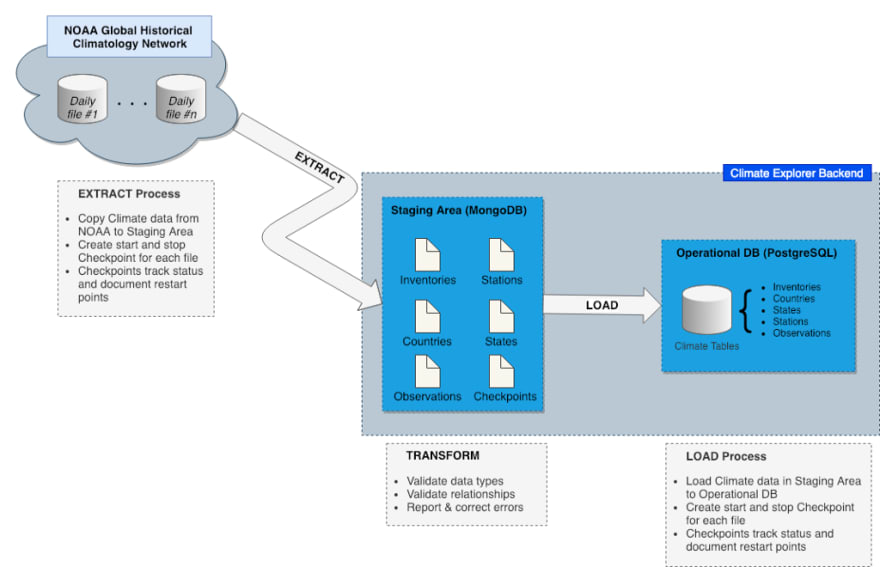
The overall goal of the ETL process is to get data from its source to an operational database. Each phase in the ETL process has a specific objective and set of constraints:
- Extract — Obtain and stage daily climate observations from the NOAA site in a way that anticipates failure and supports automatic recovery.
- Transform — Cleanse the data and organize it in a way that supports fast loading into the operational database.
- Load — Populate the operational database from the staging area. Loading the operational database must be efficient, and it must support incremental loading since new weather observations arrive daily.
Extract Procedure
The extract procedure uses the file transfer protocol (FTP) to retrieve daily weather observation files from the NOAA site as follows:
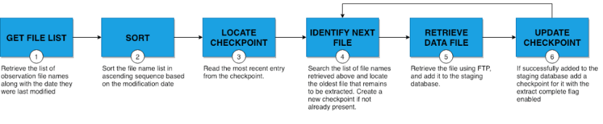
Extraction starts by retrieving the entry for the most recently completed file from the checkpoint. Checkpoint entries define the state of each file encountered during previous runs and are used to determine which file to start from in the current execution.
- file name
- modification date
- ETL state — extraction complete, transformation complete, and load complete
The starting point will be one of the following, in order of priority:
- The most recent checkpoint entry that was started, but not completed. This is the case if all three ETL state flags are disabled.
- A file name not previously encountered
- A file whose modification date is more recent than its checkpoint entry.
For the initial load of the staging area, this process may use a configuration option to control the duration of the run based on either elapsed time or a file count. Once the initial data load has been completed this process may be scheduled to run as needed to add new or modified files created by observation stations.
The last step in the extract process is particularly important since it ensures that if the current run is interrupted the next run will repeat processing of the current file.
It is crucial to have a robust error handling strategy that considers edge cases. For example, failing to notify the DevOps team to take corrective action when errors are detected can result in undesirable side effects such as repeatedly processing the same file on each run.
Transformation Procedure
The transformation procedure is responsible for analyzing the raw data added to the staging area in the following steps:

The primary objective of the transformation procedure is not only to ensure that documents and fields are valid but to automatically correct errors whenever possible. This may include modifying source data, excluding documents when there is no corrective action, logging errors, and notifying the appropriate personnel in the event of a catastrophic failure.
This includes ensuring that relations between documents contain the correct shared field values on both sides of each relation in preparation for loading into the SQL operational database.
Load Procedure
The last step in the ETL process is to transfer the staged data to the operational database. It might sound like a simple task, but the operational database is a SQL DBMS, so data must be inserted in a manner that takes into account the relationships between tables.
Since SQL relationships are based on shared column values insertion of new data starts with parent table rows followed by the related child table rows. This can become difficult as the number and complexity of relationships between tables increases.
Consider the case shown in Figure 4. Since the Region table is a parent of both the Customer and SalesRep tables, and since a one-to-many relationship exists between Customer and SalesRep, related rows are added to the Region table, then SalesRep, and finally Customer. Attempting to insert a Customer row before its associated parent Region or SalesRep would result in the violation of a foreign key constraint.
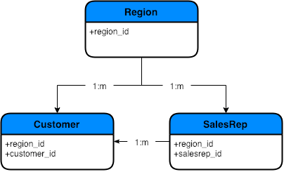
Figure 5 presents a more complicated example where one of the tables, Part, participates in a nested relationship with itself. This kind of relationship is also known as a bill of materials relationship. In other words, one where a single table contains multiple subcomponents made up of other subcomponents and parts.
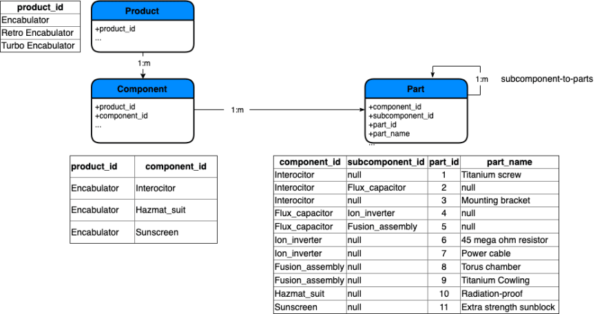
In this example, inserting rows into the Part table may be performed in one of two ways.
The first is to group input records by product and component in a way that allows the relationship to be built from the “bottom up” to ensure that a child isn’t added before its parent. Parts with no subcomponents are loaded first, then subcomponents that are parents of parts, and so on up the relationship chain.

The second option is to remove the relationship on the Parts table, insert new rows, and then re-establish the relationship. Although viable for an initial data load the fact that downtime is required and thus impacts the user makes it an option of last resort.
Luckily, the entity-relationships in Climate Explorer are relatively straightforward, so this situation isn’t applicable.
Designing the Staging Database
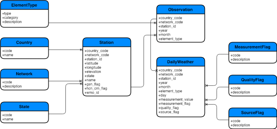
Climate Explorer’s staging database uses a set of MongoDB collections with imported file types mapped to unique collections. For example, ghcnd-stations.txt is loaded into the Station collection. Figure 7 shows the staging database collections and their logical relationships.
The MongoDB archive containing the staging database definitions is located here in the Climate Explorer repo on Github.
Database Normalization
The daily files containing weather data from stations includes an array of up to 31 observations, one for each day of the month. Data added into the staging database observations is split across two collections — the parent identifying the observations station, year, and month and its children for each daily observation.
Collections are also defined for the codes used in the Station, Observation, and DailyWeather documents. Rather than relying on documentation in readme.txt, as is the case in the NOAA files, lookup tables provide authoritative definitions for encoded fields. For example, the Network table defines the network codes used in the Station table.
Nothing prohibits importing information into the staging area without modification. Instead, we’ve opted to normalize the staged data to simplify the process of loading data into the operational database in the ETL load phase.
See the section “Designing the Operational Database” below for more information about normalization.
Schema Validation

Document updates and insertions are validated using MongoDB schema validators defined on each collection. Validators in Climate Explorer collections only perform field type checking. Analysis of field content is left to the transformation logic since the goal is to limit the number of rejected records by automatically correcting errors.
Relations, Embedded Documents, & Indexes
Since the state of the NOAA data is unknown at this time, we’ve chosen not to use relations or embedded documents in the staging database. The data must first be analyzed and cleansed to ensure the validity of the logical relationships.
Indexes are defined for all document fields on the “many” side of a relation, and on the “one” side based on document volume as is the case for the Station and Observation documents.
Extra Document Fields
The extraction process relies on MongoDB transactions to commit or rollback a file in its entirety based on whether or not an error occurred. Since there is no use case for record level recovery/restart document fields defining where data is imported from or when the import occurred are needed.
Designing the Operational Database
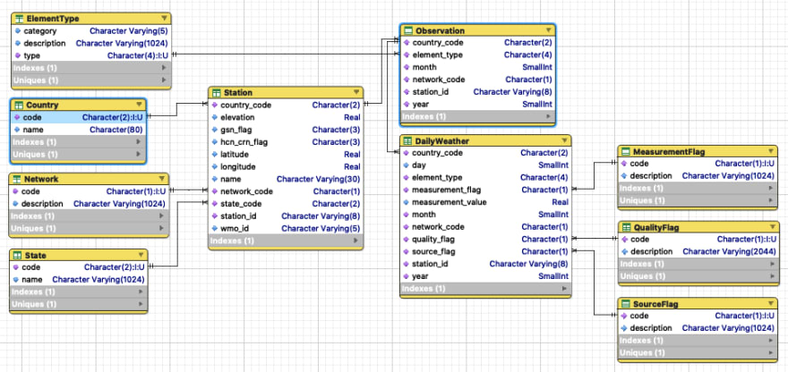
The responsibility of the operational database is to support Climate Explorer’s ability to satisfy user queries. This database is the permanent home for climate data and is implemented as a set of PostgreSQL tables and relationships.
The PostgreSQL script that defines the operational database is located here in the Climate Explorer repo on Github.
Updates & Indexes
Updates to climate data are prohibited since the system of record is the NOAA Global Historical Climatology Network. Due to this the operational database is designed for fast queries rather than updates.
Indexes are defined on both parent and child columns in a relation. No additional indexes have been created, but new ones will be added later as dictated by performance requirements.
Database Normalization
Much of the database normalization process was performed during the design of the staging database. This is driven by the assumption that minimizing the load time of the operational database is a higher priority than reducing the load time of the staging database.
Retrospective — Failing Forward
Retrieving Files Using FTP
As previously mentioned the extract process uses the file transfer protocol (FTP) to retrieve files from the NOAA site. The NPM package promise-ftp provides an interface to the FTP protocol, and the middleware module FTPAPI.js provides an interface between it and the app.
Establishing a connection to the source requires that an FTP session is created from dataSources in the Apollo context object as shown below.
// Data sources required by the resolvers. These are available to
// subclasses of DataSource via config.context.
const ftpSession = new FTPAPI( {
  host\_url: process.env.NOAA\_FTP\_URL,
  host\_port: process.env.NOAA\_FTP\_PORT,
  user: process.env.NOAA\_FTP\_USER,
  password: process.env.NOAA\_FTP\_PASSWORD
} );

const mongo = new MongoAPI();
const postgres = new PostgresAPI();
const country = new Country(mongo);
const location = new Location(postgres);
const user = new User(mongo);

const dataSources = () => ({
  ftpSession: ftpSession,
  country : country,
  location: location,
  user: user,
});

.
    .
    .

// Create and start the Apollo Server
const server = new ApolloServer({
  typeDefs,
  dataSources,
  context,
  resolvers,
});
The following example from Countries.js demonstrates the retrieval of files from the source.
async extractCountriesFromGhcnd() {
  const ftpSession = this.context.dataSources.ftpSession;
  return new Promise(function (resolve, reject) {
    ftpSession.connect()
    .then(() => {
      return ftpSession.getFile(`${process.env.NOAA_FTP_GHCN_DIRECTORY}/${process.env.NOAA_FTP_COUNTIES_FILE}`
      );
    })
    .then(stream => {
      let countries = '';
      stream.on('readable', function() {
        let data;
        while (data = this.read()) {
          countries += data.toString();
        }
        resolve(countries);
        ftpSession.disconnect();
      });
    })
    .catch(err => {
      throw new Error('FTP from NOAA failed.')
    });
  })
  .then(countries => {
    const countriesObject = this.convertToObject(countries);
    return countriesObject;
  })
  .catch(err => {
    throw new Error('FTP from NOAA failed.');
  });
}
Cleaning Up the Staging Database
When should data be removed from the staging area? There is no reason to retain data in the staging database once it is successfully added to the operational database. Two situations influence this:
- Load failure. Wrapping a load of each file in a SQL transaction forces all inserts to be rolled back if the load fails, thus enforcing the requirement that all insertions must be successful before any can be committed.
- Bad Data. Even though loading a file may be successful it’s possible that an integrity issue may be discovered later. It’s safe to assume that the probability of this occurring will diminish over time.
Based on this staging data will be retained until the start of the next load run.
Wrapping It Up

The purpose of database design is to organize data in a way that makes it easy to access and manipulate. Developing a solid database design requires matching application requirements and data flow with the capabilities provided by the DBMS. This approach has been followed in this article to complete the design of the staging and operational databases.
As dictated by an Agile approach, known requirements have been taken into consideration, and assumptions and “blue sky” ideas that have yet to materialize as requirements have been documented, but not acted on. This means revisions will become necessary if changes arise to existing requirements or new ones surface.
We’ll undoubtedly encounter this in the next article where we’ll implement the ETL process. Get ready for some code!
Up Next — Part 4, Extracting, Transforming, & Loading Data


Top comments (0)