Problem
I want to make digital gauges/indicators for my car without having to sit in my car.
Planning
I had a general idea of what I needed to do, have my OBD (Onboard diagnostics) device talk to an Arduino and the Arduino send messages back acting like a car's ECU (electronic control unit). That the OBD device then relays the messages to whatever I have connected to it.
It's worth noting that the OBD device I used is built on the ELM327 platform. I use a Vgate iCar Pro, but all the cheap OBD devices are practically the same. Just they have different cases or different ways of connecting to your phone/computer e.g. WiFi, BLE, or a physical connection. The iCar Pro uses BLE to make it easy to connect to a phone or other BLE-enabled devices, that's why I picked it.
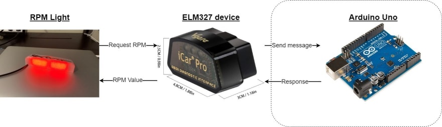
For this blog post, I'm focusing on the area within the dotted rectangle. The Arduino receiving and responding to requests from the OBD device.
How?
With my rough idea I then had to figure out how to receive and respond to messages from the OBD device, so how does a car normally do it?
The majority of cars use something called a Controller Area Network (CAN). The CAN allows lots of sensors (or anything) to talk over a common bus (CAN bus) without being interconnected like a mesh, useful for reducing the amount of wire in a car. CAN data frames with (somewhat) standardised ids are sent over the CAN bus. For this project, all I need is the RPM parameter id but there are many others. I found this handy tool that shows most of the common CAN ids with data frame examples (https://www.csselectronics.com/pages/OBD-pid-table-on-board-diagnostics-j1979).
So to get my Arduino and OBD device talking I need to have them connected to each other using a CAN bus and sending CAN data frames. I then needed to figure out how to implement the CAN. So, what are my options?
As this is a weekend project I wanted it to be cheap but also a learning opportunity so I looked up microcontrollers that implement the CAN protocol and the required electronics to get it working. But at the time there was still a backlog after COVID and these microcontrollers were not available. So I went with the quickest and more expensive option, ordering an MCP2515 module.
These modules come with everything you need to start sending messages over a CAN bus. I just had to hook mine up to the Arduino and the OBD device.
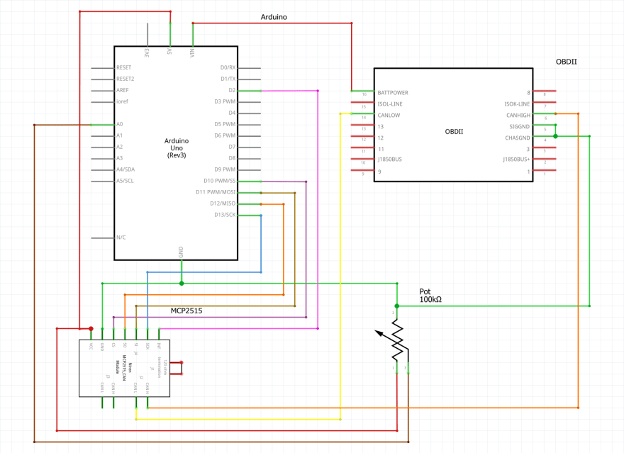
So with the added MCP2515 module the diagram above now looks like something below, with the MCP2515 handling the CAN and the Arduino deciding what to do with the messages.

Assembling
With a plan, I then had to figure out how to wire up the OBD device, MCP2515 and Arduino. As the MCP2515 is a fairly common module there's lots of documentation on how to wire them up to an Arduino.
In addition I also wired up a potentiometer to change the RPM value. This isn't needed as you can randomise values sent back in the code, but it's nice to have. I also included an OBD female connection to make connecting the OBD device easy. Without one, you'll have to manually wire the MCP2515 to the OBD device’s pins everytime you move the OBD device from your car to the sim.

A couple of things to note while wiring are:
The VIN (voltage in) needs to be 12v as your OBD device will likely want 12v as if it was plugged into a car. So if you're using something that doesn’t step down the voltage on the VIN for your microcontroller to 5v or 3.3v your probably going to melt your microcontroller.
For this setup, you will want to bridge the J1 header pins on the MCP2515 which adds 120 ohms of resistance to the CAN bus. If you were connecting the MCP2515 directly to a car you wouldn’t need to do this.
I also designed a 3D printable box to house the ECU sim and potentiometer with an OBD port. That can be found here: https://www.thingiverse.com/thing:5532047
Code
So with the assembly done, we can move to the code. For smaller hardware-related projects like this, I like to use the Arduino framework with PlatformIO.
The code for my purposes needs to:
Utilise the potentiometer
Utilise the MCP2515 module
Handle incoming RPM messages
Build RPM CAN messages
Send RPM message responses back
I'll go through each step and then have the final product (you can skip to the end if you just want the code).
Utilising the potentiometer, reading the resistance value from the potentiometer is very simple with the Arduino framework. All we have to do is use the analogRead function and the header name that we plugged the potentiometer signal wire into. In our case A0 so to assign the potentiometer to a variable would look something like int potent_rpm = analogRead(A0);.
Utilise the MCP2515 module, I'm not remaking the wheel for this project and there are lots of libraries that handle the CAN side of things. I used https://github.com/autowp/arduino-mcp2515 as it has documentation and supports sending and receiving CAN messages.
Handle incoming RPM messages, When the ECU sim gets an incoming message from the OBD device all it needs to care about is the CAN parameter id. So we can use a switch statement and use the parameter id to determine what to send.
e.g.
    unsigned char p_id = read_can_msg.data[2];

    switch (p_id)
      {
      case 0:
        ...
        break;

      case 12:
        ...
        break;

      default:
        break;
      }
Build RPM CAN messages, now that we know what messages we're receiving we can send back a response. With the library, we included we can build a message to send back to the OBD device. Again using the tool from CSS electronics you can find examples of what to send back. The switch statement would then look something like:
    unsigned char p_id = read_can_msg.data[2];

    switch (p_id)
      {
      case 0:
        write_can_msg.can_id  = 2024;
        write_can_msg.can_dlc = 8;
        write_can_msg.data[0] = 6;
        write_can_msg.data[1] = 65;
        write_can_msg.data[2] = 0;
        write_can_msg.data[3] = 255;
        write_can_msg.data[4] = 255;
        write_can_msg.data[5] = 255;
        write_can_msg.data[6] = 255;
        write_can_msg.data[7] = 170;

        mcp2515.sendMessage(&write_can_msg);
        break;

      case 12:
        write_can_msg.can_id  = 2024;
        write_can_msg.can_dlc = 8;
        write_can_msg.data[0] = 4;
        write_can_msg.data[1] = 65;
        write_can_msg.data[2] = 12;
        write_can_msg.data[3] = potent_rpm;
        write_can_msg.data[4] = 0;
        write_can_msg.data[5] = 170;
        write_can_msg.data[6] = 170;
        write_can_msg.data[7] = 170;

        mcp2515.sendMessage(&write_can_msg);
        break;

      default:
        break;
      }
You might've noticed case 0 and I added that as I found that OBD mobile apps that I used to debug the ECU sim often request that first, to see all the supported CAN parameter ids on the ECU. If the apps don't get a response to that message they will often timeout.
The final ECU sim if you just want to steal looks like this:
#include <SPI.h>
#include <mcp2515.h>

struct can_frame read_can_msg;
struct can_frame write_can_msg;
MCP2515 mcp2515(10);


void setup() {
  Serial.begin(9600);

  mcp2515.reset();
  mcp2515.setBitrate(CAN_500KBPS, MCP_8MHZ);
  mcp2515.setNormalMode();
}

void loop() {
  if (mcp2515.readMessage(&read_can_msg) == MCP2515::ERROR_OK) {
    int potent_rpm = analogRead(A0) / 10;
    unsigned char p_id = read_can_msg.data[2];

    switch (p_id)
      {
      case 0:
        write_can_msg.can_id  = 2024;
        write_can_msg.can_dlc = 8;
        write_can_msg.data[0] = 6;
        write_can_msg.data[1] = 65;
        write_can_msg.data[2] = 0;
        write_can_msg.data[3] = 255;
        write_can_msg.data[4] = 255;
        write_can_msg.data[5] = 255;
        write_can_msg.data[6] = 255;
        write_can_msg.data[7] = 170;

        mcp2515.sendMessage(&write_can_msg);
        break;

      case 12:
        write_can_msg.can_id  = 2024;
        write_can_msg.can_dlc = 8;
        write_can_msg.data[0] = 4;
        write_can_msg.data[1] = 65;
        write_can_msg.data[2] = 12;
        write_can_msg.data[3] = potent_rpm;
        write_can_msg.data[4] = 0;
        write_can_msg.data[5] = 170;
        write_can_msg.data[6] = 170;
        write_can_msg.data[7] = 170;

        mcp2515.sendMessage(&write_can_msg);
        break;

      default:
        break;
      }
  }
}
Some notes that might help if you have issues:
The baud rate may differ as I’m using an Arduino Uno clone Serial.begin(9600);.
I’m dividing my potentiometer value by ten int potent_rpm = analogRead(A0) / 10; as I had one with pretty high resistance.
The line mcp2515.setBitrate(CAN_500KBPS, MCP_8MHZ); should match the clock that’s installed on your MCP2515 module. Mine is 8MHz but I’ve seen other modules with 16Mhz
The final result
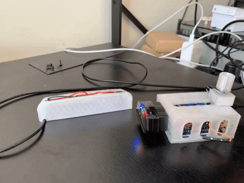
With everything hooked up and the code uploaded to the Arduino, the final product does exactly what I wanted. I’ve been able to set up a shift light that I wouldn’t have been able to do in my car very easily. Not without redlining my car everytime I want to see if the light was working.
I have plans to read the manifold pressure and calculate the boost in PSI as for some reason my car that comes with a turbo from the factory does not indicate that the turbo's active.
A slightly different topic than most on dev.to but when I was looking around for help to make this I would’ve liked a more guided approach. Instead of spec sheets and crazy-looking timing diagrams.


Top comments (1)
Excelente aporte