Introduction
To be honest, this was not a post I was planning on at first. However, I was working on a side project that I needed to use DMA for, and getting it to work with the HAL was thus far the most painful experience I faced in embedded Rust. As a result, I figured I must write about it hoping it would benefit others. What was quite interesting was that, compared to other STM32 peripherals at the HAL, DMA was a different animal. Typically when I struggled with figuring stuff out or finding proper documentation I used to cross over to other STM32 HALs to find insight as there were many similarities. This was not the case for DMA as each HAL seemed to have its own way of doing DMA implementation.
Well, I guess enough complaining, for now, 😁 so let me get into it.
In this post, I will be setting up the STM32F4 DMA engine to collect ADC samples from two microphones and print the values out to the console using UART. I will also be using the RTIC framework that I introduced in my last post.
If you find this post useful, and if Embedded Rust interests you, stay in the know and skyrocket your learning curve by subscribing to The Embedded Rustacean newsletter:
Subscribe Now to The Embedded Rustacean
📚 Knowledge Pre-requisites
To understand the content of this post, you need the following:
- Basic knowledge of coding in Rust.
- Familiarity with the basic RTIC template in Rust.
- Familiarity with DMA engines.
- Familiarity with interrupts in Cortex-M processors.
💾 Software Setup
All the code presented in this post in addition to instructions for the environment and toolchain setup are available on the apollolabsdev Nucleo-F401RE git repo. Note that if the code on the git repo is slightly different then it means that it was modified to enhance the code quality or accommodate any HAL/Rust updates.
🛠 Hardware Setup
Materials

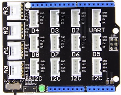
- 1 x Seeed Studio Grove Base Shield V2.0
- 2 x Seeed Studio Analog Microphone.

🔌 Connections
- The first Microphone signal pin is connected to pin PA0 (Grove Connector A0).
- The second Microphone signal pin is connected to pin PA4 (Grove Connector A2).
- The UART Tx line that connects to the PC through the onboard USB bridge is via pin PA2 on the microcontroller. This is a hardwired pin, meaning you cannot use any other for this setup. Unless you are using a different board other than the Nucleo-F401RE, you have to check the relevant documentation (reference manual or datasheet) to determine the number of the pin.
👨🎨 Software Design
There isn't much of an algorithm design for this application as most of the work is going to be handled by hardware through interrupts. In software, however, we will mainly be configuring the DMA and collecting and processing microphone samples once they become available.
The state machine below expresses how the application works.

The application will be sitting idle until a timer interrupt event happens at a rate of our choice (for example every one second). In the timer interrupt task, we will kick off an ADC sequence conversion that will go and collect ADC samples from all microphone channels. The application would then return to the idle state again and wait until a DMA event happens. The DMA event signals that the ADC data is available in memory to read. As such, in the "Transfer Complete" state the application would collect the available data, transmit it, and then return to idle.
📝 Note
An alternative approach would have been to skip the timer interrupt kicking off the ADC conversion altogether and instead have the DMA interrupt collect data directly when it becomes available by the ADC. That would require that the ADC peripheral itself support the behavior in hardware where the next conversion is automatically started (which it is in the stm32f4). This also means that the ADC conversion has to be kicked off right after the configuration is complete.
Let's now jump into the code implementation.
👨💻 Code Implementation
Note here that I will be using the RTIC framework, so the structure in this section will follow that of an RTIC frame work application (refer to this post for more detail).
📱 The app module
📥 Crate Imports
In this implementation, the crate imports include the core::fmt::Write crate for UART message formatting and the namespaces for all the various types needed from the stm32f4xx_hal crate for the ADC, DMA, Timer, and UART.
    use core::fmt::Write;
    use stm32f4xx_hal::{
        adc::{
            config::{AdcConfig, Clock, Dma, Resolution, SampleTime, Scan, Sequence},
            Adc,
        },
        dma::{config::DmaConfig, PeripheralToMemory, Stream0, StreamsTuple, Transfer},
        pac::{self, ADC1, DMA2, TIM2, USART2},
        prelude::*,
        serial::{config::Config, Tx},
        timer::{CounterHz, Event},
    };
Additionally, for convenience, the following alias is created for a DMA transfer:
type DMATransfer =
        Transfer<Stream0<DMA2>, 0, Adc<ADC1>, PeripheralToMemory, &'static mut [u16; 2]>;
This follows the DMA Transfer type signature from the stm32f4xx_hal::dma module in the hal documentation:
pub struct Transfer<STREAM, const CHANNEL: u8, PERIPHERAL, DIRECTION, BUF>
More detail on the individual members will follow in the DMA configuration section, so if this is still not clear don't worry.
🗄 Shared Resources
In the Shared struct the only entity that needs to be allocated as a shared resource is 'transfer' which is of type DMATransfer. transfer will be needed by the DMA interrupt task/ISR to enable access tp the DMA and retrieve the converted ADC data. Additionally, transfer will be needed by the timer interrupt task to kick off the next ADC conversion as transfer will own the ADC peripheral.
#[shared]
struct Shared {
   transfer: DMATransfer,
}
📁 Local Resources
In the 'Local' resources struct I include the USART transmitter, the timer counter, and finally, the buffer that the DMA will utilize. Note that the type of buffer is Option<&'static mut [u16; 2]> which also will be explained in more detail downstream.
    #[local]
    struct Local {
        tx: Tx<USART2>,
        buffer: Option<&'static mut [u16; 2]>,
        timer: CounterHz<TIM2>,
    }
tx and buffer will be utilized only by the DMA interrupt task, and timer will be utilized only by the timer interrupt task.
The #[init] Task
Note that compared to prior posts where I was not using the RTIC, the #[init] task essentially replicates the configuration part of the code.
In the application, I'll be using two buffers for DMA. The way it works is that the DMA will fill the first buffer and trigger an interrupt when it's done. At that point, the DMA will need a second buffer to start the next transfer with, making the first buffer available to extract data from. Since the DMA will be running for the whole application time, I'd need to pre-allocate 'static buffers that live for the life of the program and can cross tasks. From the RTIC documentation, it is stated that creating local resources in #[init] and #[idle] give them 'static lifetimes. As such, two [u16; 2] buffers are allocated in #[init] as follows:
#[init(local = [first_buffer: [u16; 2] = [0; 2],second_buffer: [u16; 2] = [0; 2]])]
The size of the buffers are [u16; 2] because the ADC generates a u16 result and there will be two values/samples to buffer per transaction. One from the first microphone and another from the second microphone.
🎛 Peripheral Configuration
To access the device peripherals conveniently I create a dp handle as follows:
let dp: pac::Peripherals = cx.device;
🕰 Clocks Configuration
To configure the clocks, as I have done several times before in prior posts, the RCC peripheral needs to be first constrained to access the cfgr struct. The different clocks are then configured before they are frozen using the freeze method as follows:
let rcc = dp.RCC.constrain();
let clocks = rcc
  .cfgr
  .use_hse(8.MHz())
  .sysclk(84.MHz())
  .hclk(84.MHz())
  .require_pll48clk()
  .pclk2(21.MHz())
  .freeze();
📝 Note
If you are wondering how I obtained the clock values there are several ways. Some clocks are fixed and given by the board I am using like the
hsebut others need to be calculated based on the clock tree configuration required. One could resort to the reference manual but that might be prone to errors. I instead leverage the CubeMX tool by STMicroelectronics to configure the clocks in the way I need and then copy over the values to my code.
🕹 ADC Configuration
1️⃣ Obtain handles and configure the microphone signal pins PA0 and PA4: this is similar to what I've done before here:
let gpioa = dp.GPIOA.split();
let mic1 = gpioa.pa0.into_analog();
let mic2 = gpioa.pa4.into_analog();
2️⃣ Configure the ADC Peripheral: for configuring the ADC, in the past post, I went for the default configuration. Here, I can't do that because I need to change the scan mode and also enable the dma. I create an adc_config handle that I will pass later when I initialize the ADC function as follows:
let adc_config = AdcConfig::default()
    .dma(Dma::Continuous)
    .scan(Scan::Enabled)
    .resolution(Resolution::Ten)
    .clock(Clock::Pclk2_div_8);
Here Dma, Scan, and Clock, are all enums containing configuration options. The dma method is changes the config to Continous mode. This enables the DMA to continuously obtain ADC readings. The scan method is enabling scan mode configuring the ADC to "scan" all channels and generate a result. The resolution method is changing the resolution to 10. Finally, the clock method is introducing a clock divider to slow down (reduce) the ADC clock frequency by a factor of 8. There's actually no particular reason why I've done the clock slow down, I only wanted to experiment. Typically though, one would alternate the clock to control the sample rate of the ADC.
3️⃣ Initialize ADC peripheral and obtain handle: This is exactly the same as what I have done in an earlier post and is as follows:
let mut adc = Adc::adc1(dp.ADC1, true, adc_config);
4️⃣ Configure individual Channels: This is something new. Since I'll be doing scan mode, the individual channels (one for each microphone) need to be configured. This is because the ADC needs to know two things about each channel; the sequence order and the sample time. This is because the STM32 allows one to control the order in which samples are taken in a scan sequence in addition to the sample time per channel. To do that there is a configure_channel method in the stm32f4xx-hal documentation that has the following signature:
pub fn configure_channel<CHANNEL>(
    &mut self,
    _channel: &CHANNEL,
    sequence: Sequence,
    sample_time: SampleTime
)
As such, I am required to pass a reference to the channel, the sequence order for that channel, and finally the sample time. This results in the following code:
adc.configure_channel(&mic1, Sequence::One, SampleTime::Cycles_480);
adc.configure_channel(&mic2, Sequence::Two, SampleTime::Cycles_480);
For each channel, in the first parameter, I pass the handler for each of the microphones (channel to configure). Next, sequence is passed a Sequence enum that defines where in the sequence to sample the channel at hand. Finally, sample_time is passed a SampleTime enum that contains all the sample time defining how many clock cycles to sample for. These values come from the datasheet in which I am configuring each channel to take 480 clock cycles to acquire a sample.
🧮 Serial Configuration
The serial configuration remains exactly the same as I've done several times before in prior posts (the original post for configuring serial is here):
let tx_pin = gpioa.pa2.into_alternate();
        let tx = dp
            .USART2
            .tx(
                tx_pin,
                Config::default()
                    .baudrate(115200.bps())
                    .wordlength_8()
                    .parity_none(),
                &clocks,
            )
            .unwrap();
⏳ Timer Configuration
I'll need a timer as mentioned earlier to kick off the ADC conversion at regular intervals. to configure the timer it needs to be initialized to obtain a handle, then set up a listener to generate interrupts on update events, and finally, start the timer with a 1000 Hz interrupt rate. This is done in the following lines (for more detail refer to timer interrupt post):
let mut timer = dp.TIM2.counter_hz(&clocks);
timer.listen(Event::Update);
timer.start(1000.Hz()).unwrap();
🚂 DMA Configuration
1️⃣ Split and obtain a handle for DMA: Each DMA consists of multiple streams, sort of like how GPIO consists of multiple pins per port. To obtain access to the streams we have to do something similar to split and constrain used with GPIO and RCC (I talked about split and constrain in more detail here). This is done using the StreamsTuple::new method which splits the DMA peripheral into streams (why the method wasn't called split beats me, just one of the inconsistencies in DMA I referred to earlier). The new method has the following signature which simply takes a DMA instance:
pub fn new(_regs: DMA) -> Self
I will be using DMA2 since according to the reference manual it is the entity that connects to ADC1. I create a dma handle as follows:
let dma = StreamsTuple::new(dp.DMA2);
2️⃣ Configure DMA: Similar to other peripherals that need configuration like the ADC, there is a default configuration that exists. One would only need to modify the parts that need to change. As I had expressed in earlier posts, in order to access what the default configuration was, I had to always dig into the source code. Here is the default configuration I've found:
    impl Default for DmaConfig {
        fn default() -> Self {
            Self {
                priority: Priority::Medium,
                memory_increment: false,
                peripheral_increment: false,
                transfer_complete_interrupt: false,
                half_transfer_interrupt: false,
                transfer_error_interrupt: false,
                direct_mode_error_interrupt: false,
                fifo_error_interrupt: false,
                double_buffer: false,
                fifo_threshold: FifoThreshold::QuarterFull,
                fifo_enable: false,
                memory_burst: BurstMode::NoBurst,
                peripheral_burst: BurstMode::NoBurst,
            }
        }
    }
Also similar to other peripherals, the hal dma documentation provides methods that allow modifying the individual fields. For my purposes, there are only two fields that need to be changed. transfer_complete_interrupt has to be made true so that I get an interrupt after the completion of each DMA transaction. Also memory_increment needs to be made true so that the DMA increments memory addresses for the new data by itself. For more details on DMA in the stm32f4 devices, I highly recommend reading this application note. Using the appropriate methods, a dma_config handle is created to contain the DMA config and looks as follows:
let dma_config = DmaConfig::default()
    .transfer_complete_interrupt(true)
    .memory_increment(true);
3️⃣ Initialize DMA transfer and create handle: This is the final step in the configuration where I need to initialize the type of transfer we want the DMA to do. DMAs can do peripheral to memory, memory to memory, and memory to peripheral transfers. Here I need a peripheral (the ADC) to memory transfer. In the documentation under the dma::Transfer struct implementation there is an init_peripheral_to_memory method with the following signature:
pub fn init_peripheral_to_memory(
    stream: STREAM,
    peripheral: PERIPHERAL,
    buf: BUF,
    double_buf: Option<BUF>,
    config: DmaConfig
) -> Self
Resulting in the following initialization under the handle transfer:
let transfer = Transfer::init_peripheral_to_memory(
    dma.0,
    adc,
    cx.local.first_buffer,
    None,
    dma_config,
    );
The stream argument passes dma.0 which corresponds to stream 0 that is connected to adc1, the peripheral argument passes the initialized adc handle created earlier, the buf argument passes the first_buffer buffer declared in the local resources of the #[init] task, double_buf is passed None, and finally config is passed the dma_config handle created earlier containing the dma configuration. Note that double buffering is a dma feature that I'm not using and the documentation states that one should pass None when not in use.
Return Resources
Remember that at the end of the init task, the initialized values for the system-wide #[shared] and #[local] resources defined earlier must be returned. This looks as follows:
(
    Shared { transfer },
    Local {
           tx,
           buffer: Some(cx.local.second_buffer),
           timer,
          },
    init::Monotonics(),
)
Note how second_buffer got wrapped with an Option. This needed to be done as I've defined the buffer type earlier in the resources section as Option<&'static mut [u16; 2]>. Though why does second_buffer need to be wrapped with an Option? Please read on.
The Timer Interrupt Task (ADC Start State)
The timer interrupt task is the one accessed whenever a TIM2 timer event expiry happens. Earlier this was defined in the configuration to fire at a rate of 1kHz. Additionally, in the timer interrupt task, I will need to access the transfer shared resource and the timer local resource. All that needs to be done in the task to start a DMA transfer and the ADC conversion and clear the timer interrupt flag. Note that the adc peripheral is now owned by transfer so the adc methods are only accessible through the transfer handle. To start a DMA transfer the hal provides a start method with the following signature:
source
pub fn start<F>(&mut self, f: F)
where
    F: FnOnce(&mut PERIPHERAL),
This method provides a closure with a token to access the owned peripheral (in this case the ADC). As such, the timer interrupt task code looks as follows:
 #[task(binds = TIM2, shared = [transfer], local = [timer])]
    fn adcstart(mut cx: adcstart::Context) {
        cx.shared.transfer.lock(|transfer| {
            transfer.start(|adc| {
                adc.start_conversion();
            });
        });
        cx.local.timer.clear_interrupt(Event::Update);
    }
Note how the transfer resource had to be locked before it could be used since it is a shared resource. As such there are two levels of closures, the first closure provides a token to the locked resource transfer, and the second nested closure provides access to the transfer peripheral. Also, the clear_interrupt part is the same as what has been done before in the STM32F4 Embedded Rust at the HAL: The RTIC Framework post.
The DMA Interrupt Task (DMA Start State)
This is the last part of the code and where things get interesting when the DMA interrupt happens. The DMA interrupt indicates that a transfer has been completed and now there is data stored in memory that needs to be collected. Looking into the documentation again, we find a next_transfer method with the following signature:
pub fn next_transfer(
    &mut self,
    new_buf: BUF
) -> Result<(BUF, CurrentBuffer), DMAError<BUF>>
What this method does is provide a buffer (first_buffer we started the transfer with) filled with data collected from the ADC and takes a new buffer (second_buffer ) to start the next transfer with. The new buffer is passed through thenew_buf parameter and the data collected is returned in the Result<(BUF, CurrentBuffer), DMAError<BUF>>. Note that CurrentBuffer is relative to the double buffering feature that we aren't using so all I need is BUF.
To implement the code, first, the task is defined by binding the DMA2_STREAM0 interrupt that maps to the stream that connects the ADC:
#[task(binds = DMA2_STREAM0, shared = [transfer], local = [tx, buffer])]
The DMA2_STREAM0 name comes from the interrupt enum list for the stm32f4xx-hal. The task attribute also includes the list of resources that will be used in the implementation. This includes buffer that contains the second buffer that will be passed to the next rransfer. After that, for convenience, handles for the share and local resources are created:
let mut shared = ctx.shared;
let local = ctx.local;
As before, access to the next_transfer method needs to happen through the shared transfer resource so it needs to be locked before use resulting in the following:
        let buffer = shared.transfer.lock(|transfer| {
            let (buffer, _) = transfer
                .next_transfer(local.buffer.take().unwrap())
                .unwrap();
            buffer
        });
Note what is being passed to next_transfer which is local.buffer.take().unwrap(). This is why I earlier defined the buffer type as an Option<&'static mut [u16; 2]>. Here I am passing ownership of local.buffer to transfer using the take() method and leaving None in its place, then I use the unwrap() method to unwrap the Option and pass the buffer. Now, thinking about it, local.buffer has a None left inside of it. So when the next interrupt happens, at this point there is no new buffer to provide. But what was that done? The thing is that at this point is that the other buffer I'm using now tied to the buffer handle that was passed back by the dma transfer, and still has the data I want. I cannot give up ownership until I get the data I need. As a result, I would need to empty buffer first before making it available again in the resource pool for the next DMA transfer. On a side note, something important to realize here is that next_transfer also clears the dma interrupt so no special method needs to be called to do that.
To empty buffer, which is the buffer passed by the dma, I wrote the following code:
        let mic1 = buffer[0];
        let mic2 = buffer[1];
As might be obvious already, the adc collected data from multiple channels is provided back in a contiguous piece of memory (the reason why I declared the buffer as a [u16;2]). Here the data is mapped starting at index 0 to the sequence order provided earlier in the adc channel config. buffer[0] maps to the channel configured as Sequence::One and buffer[1] to Sequence::Two.
Now that the data has been obtained, the old buffer, buffer can be wrapped in a Some and written back to local.buffer in the resource pool so that it's available for the next transfer:
        // Return buffer to resources pool for next transfer
        *local.buffer = Some(buffer);
Finally, the ADC results are transmitted over UART using the writeln! macro:
        // Send over data to UART
        writeln!(local.tx, "/*{:02},{:02}*/\r", mic1, mic2).unwrap();
    }
📱 Full Application Code
Here is the full code for the implementation described in this post. You can additionally find the full project and others available on the apollolabsdev Nucleo-F401RE git repo.
#![no_std]
#![no_main]

use panic_halt as _;

#[rtic::app(device = stm32f4xx_hal::pac, dispatchers = [])]
mod app {

    use core::fmt::Write;
    use stm32f4xx_hal::{
        adc::{
            config::{AdcConfig, Clock, Dma, Resolution, SampleTime, Scan, Sequence},
            Adc,
        },
        dma::{config::DmaConfig, PeripheralToMemory, Stream0, StreamsTuple, Transfer},
        pac::{self, ADC1, DMA2, TIM2, USART2},
        prelude::*,
        serial::{config::Config, Tx},
        timer::{CounterHz, Event},
    };

    type DMATransfer =
        Transfer<Stream0<DMA2>, 0, Adc<ADC1>, PeripheralToMemory, &'static mut [u16; 2]>;

    #[shared]
    struct Shared {
        transfer: DMATransfer,
    }

    #[local]
    struct Local {
        tx: Tx<USART2>,
        buffer: Option<&'static mut [u16; 2]>,
        timer: CounterHz<TIM2>,
    }

    #[init(local = [first_buffer: [u16; 2] = [0; 2],second_buffer: [u16; 2] = [0; 2]])]
    fn init(cx: init::Context) -> (Shared, Local, init::Monotonics) {
        let dp: pac::Peripherals = cx.device;

        // Clock Configuration
        let rcc = dp.RCC.constrain();
        let clocks = rcc
            .cfgr
            .use_hse(8.MHz())
            .sysclk(84.MHz())
            .hclk(84.MHz())
            .require_pll48clk()
            .pclk2(21.MHz())
            .freeze();

        // ADC Configuration
        // Configure the first microphone pin into analog and obtain handler.
        // Split port A
        let gpioa = dp.GPIOA.split();
        // PA0 maps to A0 on Grove Base Shield
        // PA4 maps to A2 on Grove Base Shield
        let mic1 = gpioa.pa0.into_analog();
        let mic2 = gpioa.pa4.into_analog();
        // Create Handler for adc peripheral (PA0 and PA4 are connected to ADC1)
        // Configure ADC for sequence conversion with interrtups
        let adc_config = AdcConfig::default()
            .dma(Dma::Continuous)
            //Scan mode is also required to convert a sequence
            .scan(Scan::Enabled)
            .resolution(Resolution::Ten)
            .clock(Clock::Pclk2_div_8);

        let mut adc = Adc::adc1(dp.ADC1, true, adc_config);
        adc.configure_channel(&mic1, Sequence::One, SampleTime::Cycles_480);
        adc.configure_channel(&mic2, Sequence::Two, SampleTime::Cycles_480);

        // DMA Configuration
        let dma = StreamsTuple::new(dp.DMA2);
        let dma_config = DmaConfig::default()
            .transfer_complete_interrupt(true)
            .memory_increment(true)
            .double_buffer(false);

        let transfer = Transfer::init_peripheral_to_memory(
            dma.0,
            adc,
            cx.local.first_buffer,
            None,
            dma_config,
        );

        // Serial Configuration
        // Configure/Define TX pin
        // Use PA2 as it is connected to the host serial interface
        // let gpioa = dp.GPIOA.split();
        let tx_pin = gpioa.pa2.into_alternate();
        // Configure Serial perihperal channel
        // We're going to use USART2 since its pins are the ones connected to the USART host interface
        let tx = dp
            .USART2
            .tx(
                tx_pin,
                Config::default()
                    .baudrate(115200.bps())
                    .wordlength_8()
                    .parity_none(),
                &clocks,
            )
            .unwrap();

        let mut timer = dp.TIM2.counter_hz(&clocks);
        timer.listen(Event::Update);
        timer.start(1000.Hz()).unwrap();

        (
            Shared { transfer },
            Local {
                tx,
                buffer: Some(cx.local.second_buffer),
                timer,
            },
            init::Monotonics(),
        )
    }

    #[task(binds = TIM2, shared = [transfer], local = [timer])]
    fn adcstart(mut cx: adcstart::Context) {
        cx.shared.transfer.lock(|transfer| {
            transfer.start(|adc| {
                adc.start_conversion();
            });
        });
        cx.local.timer.clear_interrupt(Event::Update);
    }

    #[task(binds = DMA2_STREAM0, shared = [transfer], local = [tx, buffer])]
    fn dma(ctx: dma::Context) {
        // Destructure dma::Context to make only the shared resources mutable
        //let dma::Context { mut shared, local } = cx;

        // Also Equivalent to
        let mut shared = ctx.shared;
        let local = ctx.local;

        let buffer = shared.transfer.lock(|transfer| {
            let (buffer, _) = transfer
                .next_transfer(local.buffer.take().unwrap())
                .unwrap();
            buffer
        });

        // Read out values from buffer
        let mic1 = buffer[0];
        let mic2 = buffer[1];

        // Return buffer to resources pool for next transfer
        *local.buffer = Some(buffer);

        // Send over data to UART
        writeln!(local.tx, "/*{:01},{:02}*/\r", mic1, mic2).unwrap();
    }
}
## 🔬 Further Experimentation/Ideas
- Expand on this code such that the UART transmission is also handled by the DMA.
- Add more ADC channels and expand the code to handle them.
- Convert the Analog Temperature Sensing Application introduced before to handled by DMA.
- Refactor the existing code to run without the RTIC framework.
Conclusion
In this post, the sm32f4xx-hal DMA was leveraged to create an application that collects ADC samples from two microphones without processor interference. The code relies on interrupts and utilizes the RTIC framework as well. Creating DMA applications has proven to be a bit more challenging than other peripherals thus far due to the lack of consistency in approach among various stm hals. The application was created leveraging the STM32F401RE microcontroller on the Nucleo-F401RE development board. All code was created at the HAL level using the stm32f4xx Rust HAL. Have any questions/comments? Share your thoughts in the comments below 👇.


Oldest comments (2)
Thank you Omar, this is really helpful. I struggled with this for a while until I saw your overall implementation. This comment in your code relieved my pain:
"// Return buffer to resources pool for next transfer"
Im glad it helped! I honestly would say that DMA with the STM32F4 is probably the example I struggled with the most. It took me a while to wrap my head around the API and how it works.