
This blog post is the second one of a multi-part series of posts where I explore various peripherals in the STM32F401RE microcontroller using embedded Rust at the HAL level. Please be aware that certain concepts in newer posts could depend on concepts in prior posts.
If you find this post useful, and if Embedded Rust interests you, stay in the know and skyrocket your learning curve by subscribing to The Embedded Rustacean newsletter:
Subscribe Now to The Embedded Rustacean
Introduction
In this post, I will enhance the GPIO button-controlled blinking project in my previous post by using a timer/counter peripheral instead. In the previous post, the focus was on the GPIO peripheral and I had controlled the rate of flashing of an LED connected to a GPIO output using a button connected to a GPIO input. Even delay was created algorithmically, meaning that there was a piece of code (loop) that generated the needed delay. It was mentioned as well that using software is not ideal to create delays as it does not scale and hardware methods (ex. timer peripheral) are more appropriate. In this post, I will be enhancing the previous code by instead leveraging a timer/counter peripheral to manage the delay. This will make the delay more deterministic and scalable among different platforms. Again, I will not be using interrupts and instead would be polling a timer/counter for the elapsed time.
Knowledge Pre-requisites
To understand the content of this post, you need the following:
- Basic knowledge of coding in Rust.
- Familiarity with the basic template for creating embedded applications in Rust.
Software Setup
All the code presented in this post in addition to instructions for the environment and toolchain setup are available on the apollolabsdev Nucleo-F401RE git repo. Note that if the code on the git repo is slightly different then it means that it was modified to enhance the code quality or accommodate any HAL/Rust updates.
Hardware Setup
Materials
Connections
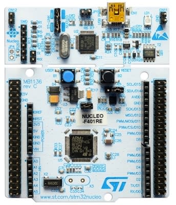
There will be no need for external connections. On-board connections will be utilized and the include the following:
- LED is connected to pin PA5 on the microcontroller. The pin will be used as an output.
- User button connected to pin PC13 on the microcontroller. The pin will be used as an input.
Software Design
The application in this post adopts the same algorithmic approach as my previous post, however, with minor modifications. Here instead of updating a loop variable to check if it had reached the maximum value I instead poll a timer/counter and check if it reached the desired delay value. Let's incorporate these adjustments into the flow chart to see how it would look like now.

🚨 Important Notes:
Delay methods come in two forms, blocking and non-blocking. Blocking means that the controller will sit idle (operations blocked) until the delay finishes. Non-blocking on the other hand means allowing operations to resume and the controller can do other things meanwhile. The code will keep returning to check (poll) the timer if the delay ended. This means that for a polling approach like ours where we need to check on the button being pressed while time passes, a non-blocking approach is required. Again, if we were using interrupts this all wouldn't matter as we would have an interrupt service routine that would inform us that the button got pressed. It's worth noting that interrupts are not affected by blocking delays unless preemption is disabled.
Let's now jump into implementing this algorithm.
Code Implementation
Crate Imports
In this implementation, three crates are required as follows:
- The
cortex_m_rtcrate for startup code and minimal runtime for Cortex-M microcontrollers. - The
fugitcrate for the handling of time in embedded systems. - The
panic_haltcrate to define the panicking behavior to halt on panic. - The
stm32f4xx_halcrate to import the STMicro STM32F4 series microcontrollers device hardware abstractions on top of the peripheral access API.
use cortex_m_rt::entry;
use fugit::{Duration, ExtU32};
use panic_halt as _;
use stm32f4xx_hal::{
    pac::{self},
    prelude::*,
};
Peripheral Configuration Code
Ahead of our application code, peripherals are configured through the following steps:
1️⃣ Obtain a handle for the device peripherals: In embedded Rust, as part of the singleton design pattern, we first have to take the PAC level device peripherals to give us access to them. This is done using the take() method. Here I create a device peripheral handler named dp as follows:
let dp = pac::Peripherals::take().unwrap();
2️⃣ Configure the system clocks: The system clocks need to be configured as they are needed in setting up the timer peripheral. To set up the system clocks we need to first promote the RCC struct from the PAC and constrain it using the constrain() method (more detail on the constrain method here) to give use access to the cfgr struct. After that, we create a clocks handle that provides access to the configured (and frozen) system clocks. The clocks are configured to use an HSE frequency of 8MHz by applying the use_hse() method to the cfgr struct. The HSE frequency is defined by the reference manual of the Nucleo-F401RE development board. Finally, the freeze() method is applied to the cfgr struct to freeze the clock configuration. Note that freezing the clocks is a protection mechanism by the HAL to avoid the clock configuration changing during runtime. It follows that the peripherals that require clock information would only accept a frozen Clocks configuration struct.
let rcc = dp.RCC.constrain();
let clocks = rcc.cfgr.use_hse(8.MHz()).freeze();
3️⃣ Promote the PAC-level GPIO structs: We need to configure the LED pin as a push-pull output and obtain a handler for the pin so that we can control it. We also need to obtain a handle for the button input pin. According to the connection details, the LED pin connection is part of GPIOA and the button connection is part of GPIOC. Before we can obtain any handles for the LED and the button we need to promote the pac-level GPIOA and GPIOC structs to be able to create handles for individual pins. We do this by using the split() method as follows:
let gpioa = dp.GPIOA.split();
let gpioc = dp.GPIOC.split();
4️⃣ Obtain a handle for the LED and configure it to an output: As earlier stated, the on-board LED on the Nucleo-F401RE is connected to pin PA5 (Pin 5 Port A). As such, we need to create a handle for the LED pin that has PA5 configured to a push-pull output using the into_push_pull_output() method. We will name the handle led and configure it as follows:
let mut led = gpioa.pa5.into_push_pull_output();
5️⃣ Obtain a handle and configure the input button: The on-board user push button on the Nucleo-F401RE is connected to pin PC13 (Pin 13 Port C) as stated earlier. Pins are configured to an input by default so when creating the handle for the button we don't call any special methods.
let button = gpioc.pc13;
Note that as opposed to the LED output, the button handle here does not need to be mutable since we will only be reading it.
6️⃣ Obtain a handle and configure a millisecond counter: Here we need first need to obtain access to a timer peripheral to access its methods. Here I chose TIM1. In order to create a counter handle, one of the available timer traits is the counter_ms trait. If you examine the list of traits there are several options. Why did I choose counter_ms? This is because of two reasons; the first is that it allows me to allocate time in milliseconds, and the second is that it is a non-blocking timer as the description indicates. Recall that I mentioned earlier that a non-blocking counter is necessary so that I can poll for a button press while the counter is counting. Looking further, counter_ms has the following signature:
fn counter_ms(self, clocks: &Clocks) -> CounterMs<Self>
You can see that the method requires a frozen clocks struct to get passed to it and returns a CounterMs type. As such, we create a counter handle counter as follows:
let mut counter = dp.TIM1.counter_ms(&clocks);
This is it for configuration. Let's now jump into the application code.
Application Code
Following the design described earlier, I first need to initialize a delay variable del_var and initialize the output of the LED. del_var needs to be mutable as it will be modified by the delay loop. I also choose to set the initial led output level to low by default. Using the same Pin methods mentioned earlier, there is a set_low() method that I use to achieve that.
    // Create and initialize a delay variable to manage delay loop
    let mut del_var: Duration<u32, 1, 1000> = 2001.millis();

    // Initialize LED to on or off
    led.set_low();
Notice here that for del_var I am using a Duration type. Why? this is because later when I want to start (trigger) the counter to start counting I will need to provide a duration for the counter. We'll see that the method in which I will be using requires that I pass a Duration type. millis() is a trait that converts a number into a Duration. Both Duration and millis() are imported from the fugit crate mentioned earlier. Note also here that the duration I created is 2001 milliseconds, this is because the counter will start counting at 0 and will count up to 2000 before it wraps back to 0.
Next inside the program loop, I first start by kicking off the counter. Examining the counter documentation for methods available there is a start method with the following signature:
pub fn start(&mut self, timeout: TimerDurationU32<FREQ>) -> Result<(), Error>
This method kicks off the timer to start counting for a specified timeout duration. The timeout parameter is of type TimerDurationU32 which is only an alias for the Duration type mentioned earlier. Additionally, it is shown that the start method returns a Result that I would need to unwrap(). The counter is kicked off as follows:
counter.start(del_var).unwrap();
Following the kick-off of the counter, I now need to keep polling the counter for the elapsed time. As part of the counter available methods, there is a now method that returns a TimerInstantU32, again an alias for an Instant type which represents an instant in time. However, in order to compare to del_var I would need to convert the returned Instant type to a Duration type somehow. In comparison, a duration represents the time between two instances. This means that somehow the duration that needs to be retrieved is the duration elapsed since the instant that the timer started. Navigating the Instant struct documentation I've located a duration_since_epoch method that returns a Duration indicating the time elapsed since the start of the counter. As such, the application loop looks as follows:
    // Application Loop
    loop {
        // Start counter with with del_var duration
        counter.start(del_var).unwrap();
        // Enter loop and check for button press until counter reaches del_var
        while counter.now().duration_since_epoch() < del_var - 1.millis() {
            // Check if button is pressed at any point
            if button.is_low() {
                // If button pressed decrease the delay value by 500 ms
                del_var = del_var - 500.millis();
                // If updated delay value drops below 500 ms then reset it back to starting value to 2 secs
                if del_var.to_millis() < 500_u32 {
                    del_var = 2001.millis();
                }
                // Exit delay loop since button was pressed
                break;
            }
        }
        // Toggle LED
        led.toggle();
    }
Here you can see that I have created a loop that keeps going around until counter reaches del_var - 1.millis() indicating a duration of 1999 equivalent to 2 seconds. As indicated in the design section, if the loop ends naturally then del_var remains unchanged. Otherwise, at any point in time while delaying, if the button is pressed I can detect it using the is_low() method. At which point I will be decreasing del_var by 500.millis() duration. If I end up with a del_var value less than 500_u32 then I am restoring the original value I started with of 2001.millis().
🚨 Important Notes:
Same as the past post, once you run the code, you'll see the LED flashing but you'll notice some weird behavior. The flashing frequencies would seem to keep changing in random order. This is because of an effect called "bouncing" on the mechanical button. Check the experimentation ideas section below for more detail.
Full Application Code
Here is the full code for the implementation described in this post. You can additionally find the full project and others available on the apollolabsdev Nucleo-F401RE git repo.
#![no_std]
#![no_main]

// Imports
use cortex_m_rt::entry;
use fugit::{Duration, ExtU32};
use panic_halt as _;
use stm32f4xx_hal::{
    pac::{self},
    prelude::*,
};

#[entry]
fn main() -> ! {
    // Setup handler for device peripherals
    let dp = pac::Peripherals::take().unwrap();

    // Set up the system clock. We want to run at 48MHz for this one.
    let rcc = dp.RCC.constrain();
    let clocks = rcc.cfgr.use_hse(8.MHz()).freeze();

    // Configure the LED pin as a push pull ouput and obtain handler.
    // On the Nucleo FR401 theres an on-board LED connected to pin PA5.
    let gpioa = dp.GPIOA.split();
    let mut led = gpioa.pa5.into_push_pull_output();

    // Configure the button pin (if needed) and obtain handler.
    // On the Nucleo FR401 there is a button connected to pin PC13.
    // Pin is input by default
    let gpioc = dp.GPIOC.split();
    let button = gpioc.pc13;

    // Create and initialize a delay variable to manage delay loop
    let mut del_var: Duration<u32, 1, 1000> = 2001.millis();

    // Initialize LED to on or off
    led.set_low();

    // Create a Millisecond Counter Handle
    let mut counter = dp.TIM1.counter_ms(&clocks);

    // Application Loop
    loop {
        // Start counter with with del_var duration
        counter.start(del_var).unwrap();
        // Enter loop and check for button press until counter reaches del_var
        while counter.now().duration_since_epoch() < del_var - 1.millis() {
            // Check if button is pressed at any point
            if button.is_low() {
                // If button pressed decrease the delay value by 500 ms
                del_var = del_var - 500.millis();
                // If updated delay value drops below 500 ms then reset it back to starting value to 2 secs
                if del_var.to_millis() < 500_u32 {
                    del_var = 2001.millis();
                }
                // Exit delay loop since button was pressed
                break;
            }
        }
        // Toggle LED
        led.toggle();
    }
}
Conclusion
In this post, an LED control application was created leveraging the GPIO and counter peripherals for the STM32F401RE microcontroller on the Nucleo-F401RE development board. All code was based on polling (without interrupts) meaning that non-blocking counters were leveraged as well. All code was created at the HAL level using the stm32f4xx Rust HAL. Have any questions? Share your thoughts in the comments below 👇.


Oldest comments (2)
github.com/aholzbaur/rust-stm32f4-...
community.st.com/t5/stm32-mcu-prod...
Hello @neuberfran , I responded to you git issue. I think your issue arises from a cargo.toml mismatch. Please check that your cargo.toml is matching. There are two issues, one is that the fugit crate is not imported. Second, it seems that you are running on a different/older version of the HAL crate. My code was on "0.13.1", it seems you are on "0.11.1".